Service Kit Installation Procedures
4–54 www.zoll.com 906-0731-04-01 Rev. C
Power Interface Module Service Kit Installation Instructions
Required Tools
• Torque driver with #1 and #2 Phillips bits
• Nut driver set
Kit Contents
Instructions
Quantity Description Depiction
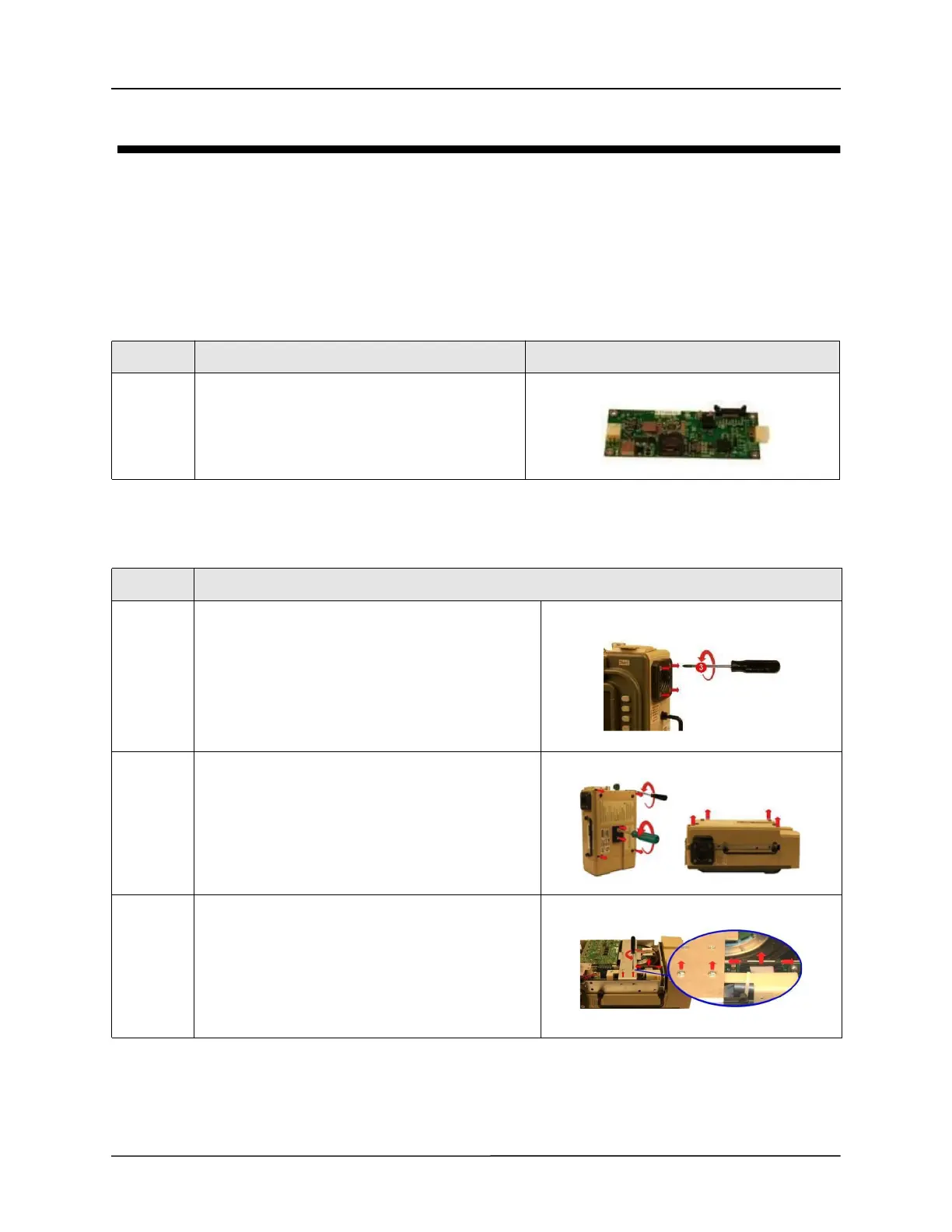
1 PIM Board (PCB)
Step Action
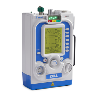
1 Loosen by 1 full turn and do not remove the four 8-
32 x 3 screws on the outer air intake. (Additional
loosening may cause the filter disk to slip out of
place)
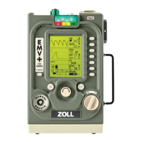
2 Loosen and remove the two 1032 Keps nuts and the
four 6-32 x 2 screws.
Save these screws and Keps nuts.
Remove the back case by lifting it from the ventilator.
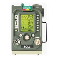
3 Remove the two 4-40 x 1/4 screws on the dovetail
mounting bracket.
Save these screws.
Disconnect the ribbon cable on the PIM board by
simultaneously applying pressure on the two ejector
latches.