Service Kit Installation Procedures
906-0731-04-01 Rev. C ZOLL Ventilator Service Manual 4–55
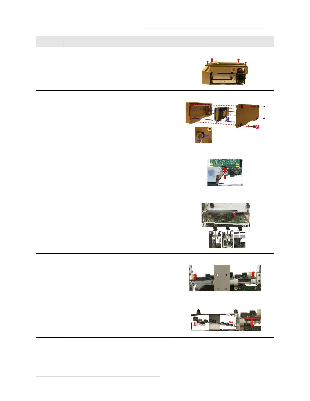
4 Flip the ventilator over and remove the front case
assembly by lifting it straight up and away from the
ventilator module.
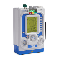
5 Remove the battery compartment cover by
unscrewing the four 6-32 x 5/16 screws.
Save these screws.
6 Remove the battery by unscrewing the four 6-32 x 2
1/4 screws and detaching the plug from its locking
latch.
Save these screws.
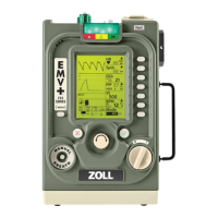
7 Disconnect the Power Input Cable from the PIM
board by pressing on the locking latch and pulling the
cable straight up from the connector.
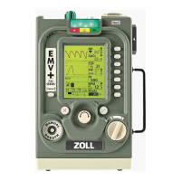
8 Loosen and remove the five 4-40 x 1/4 screws holding
the PIM board to the ventilator module.
Save these screws.
Move SpO
2
Insulator out of the way and insert
screwdriver through the holes to aid in removing
screws.
Note: Do not fold the SpO
2
Insulator.
9 Lift the defective PIM Board out of the ventilator
module.
10 Place the new PIM Board
Note: Make sure male header pins are inserted
correctly into the mating header.
Step Action