Technical Information DFS 700 / 04.2009 6-6
x2
6
7
8
1
1
2
2
3
4
5
10
11
12
13
14
15
16
x2
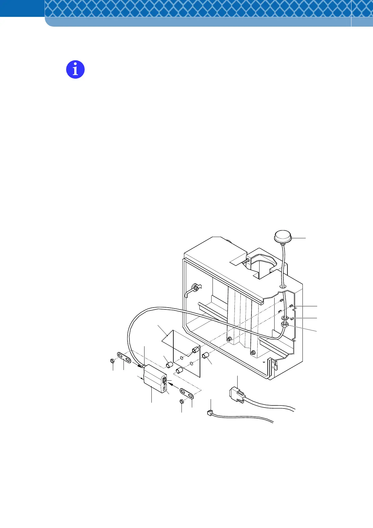
Fit the GSM/GPRS Modem into the Battery- & Mounting Box
The parts to be mounted can be found in the delivery package for the GSM/GPRS
Modem.
(1) Push one spacer ring (Figure 6-6 Item 5) onto the two bolt threads (Figure 6-6 Item 6) on
the top right in the Battery- & Mounting Box.
(2) Then push the plastic cover (Figure 6-6 Item 3) with the angled part upwards on the bolt
threads and again push on a spacer ring (Figure 6-6 Item. 4). The cover protects the
GSM Modem from dripping condensed water.
(3) On the GSM/GPRS Modem (Figure 6-6 Item 10) insert the clips (Figure 6-6 Item 2) into
the rear rail from both sides and adjust the spacing so that the GSM/GPRS Modem can
be seated on the two bolt threads. The antenna connection (Figure 6-6 Item 16) must
point to the left. Fix the GSM Modem in place with two M4-fixing screws
(4) Push the GSM antenna (Figure 6-6 Item 7) and antenna cable with the plug facing
forward through the hole in the top of the Battery- & Mounting Box and thread the
washer (Figure 6-6 Item 8) and hexagonal nut (Figure 6-6 Item 9) onto the antenna
cable.
Figure 6-6 Fitting the GSM/GPRS Modem