■
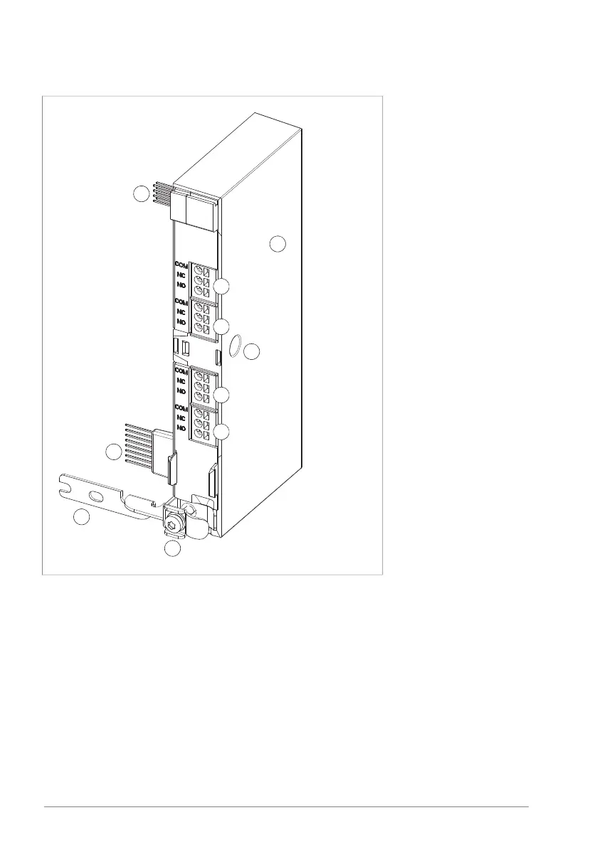
Layout
1. BREL-01 module
2. Locking screw hole
3. X103 connector
4. X104 connector
5. X105 connector
6. X106 connector
7. Internal X100 connector
8. Internal X102 connector
9. Grounding rail
10. Grounding screw
Mechanical installation
Refer to Installing options (page 86) and BAPO, BREL, BRES, and BTAC modules
quick installation guide (3AXD50000837946 [English]).
Electrical installation
Use 0.5 … 2.5 mm
2
(20 … 14 AWG) cable with a sufficient voltage rating.
If you connect an inductive load (relay or contactor coil, motor) protect the relay
contacts with a varistor, RC filter (AC) or diode (DC). Install the protective
component as close to the inductive load as possible. Do not install protective
components at the relay output terminals.
258 BREL-01 relay output extension module
 Loading...