■
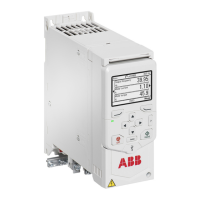
Base unit
D 1
DI2
IN1
IN2
+24V
DGND
DCOM
SGND
OUT1
RO1C
RO1A
RO1B
1
2
3
4
5
6
Connections of the base unit:
1. Auxiliary voltage output
2. Digital inputs
3. Safe torque-off connections
4. Relay output connection
5. Cold configuration adapter connection for
CCA-01
6. Front option module slot 1
Option modules
The drive supports optional extension modules on the front and on the right side.
Refer to Type designation key (page 36).
Operation principle and hardware description 33

 Loading...