Actual signals and parameters
80
7 = STARTED The drive has received a start command. Relay is energized even if Run
Enable signal is off. Relay is de-energized when drive receives a stop
command or a fault occurs.
8 = SUPRV 1 OVER Status according to supervision parameters 3201...3203.
9 = SUPRV 1 UNDER See selection SUPRV 1 OVER.
10 = SUPRV 2 OVER Status according to supervision parameters 3204...3206.
11 = SUPRV 2 UNDER See selection SUPRV 2 OVER.
12 = SUPRV 3 OVER Status according to supervision parameters 3207...3209.
13 = SUPRV 3
UNDER
See selection SUPRV 3 OVER.
14 = AT SET POINT Output frequency is equal to the reference frequency.
15 = FAULT(RST) Fault. Automatic reset after the autoreset delay. See parameter group
31 AUTOMATIC RESET.
16 = FLT/ALARM Fault or alarm
17 = EXT CTRL Drive is under external control.
18 = REF 2 SEL External reference REF2 is in use.
19 = CONST FREQ A constant speed is in use. See parameter group 12 CONSTANT SPEEDS.
20 = REF LOSS Reference or active control location is lost.
21 = OVERCURRENT Alarm/Fault by overcurrent protection function
22 = OVERVOLTAGE Alarm/Fault by overvoltage protection function
23 = DRIVE TEMP Alarm/Fault by drive overtemperature protection function
24 =UNDERVOLTAGE Alarm/Fault by undervoltage protection function
25 = AI1 LOSS Analog input AI1 signal is lost.
27 = MOTOR TEMP Alarm/Fault by motor overtemperature protection function. See parameter
3005 MOT THERM PROT.
28 = STALL Alarm/Fault by stall protection function. See parameter 3010 STALL
FUNCTION.
29 = UNDERLOAD Alarm/Fault by underload protection function. See parameter 3013
UNDERLOAD FUNC.
33 = FLUX READY Motor is magnetised and able to supply nominal torque.
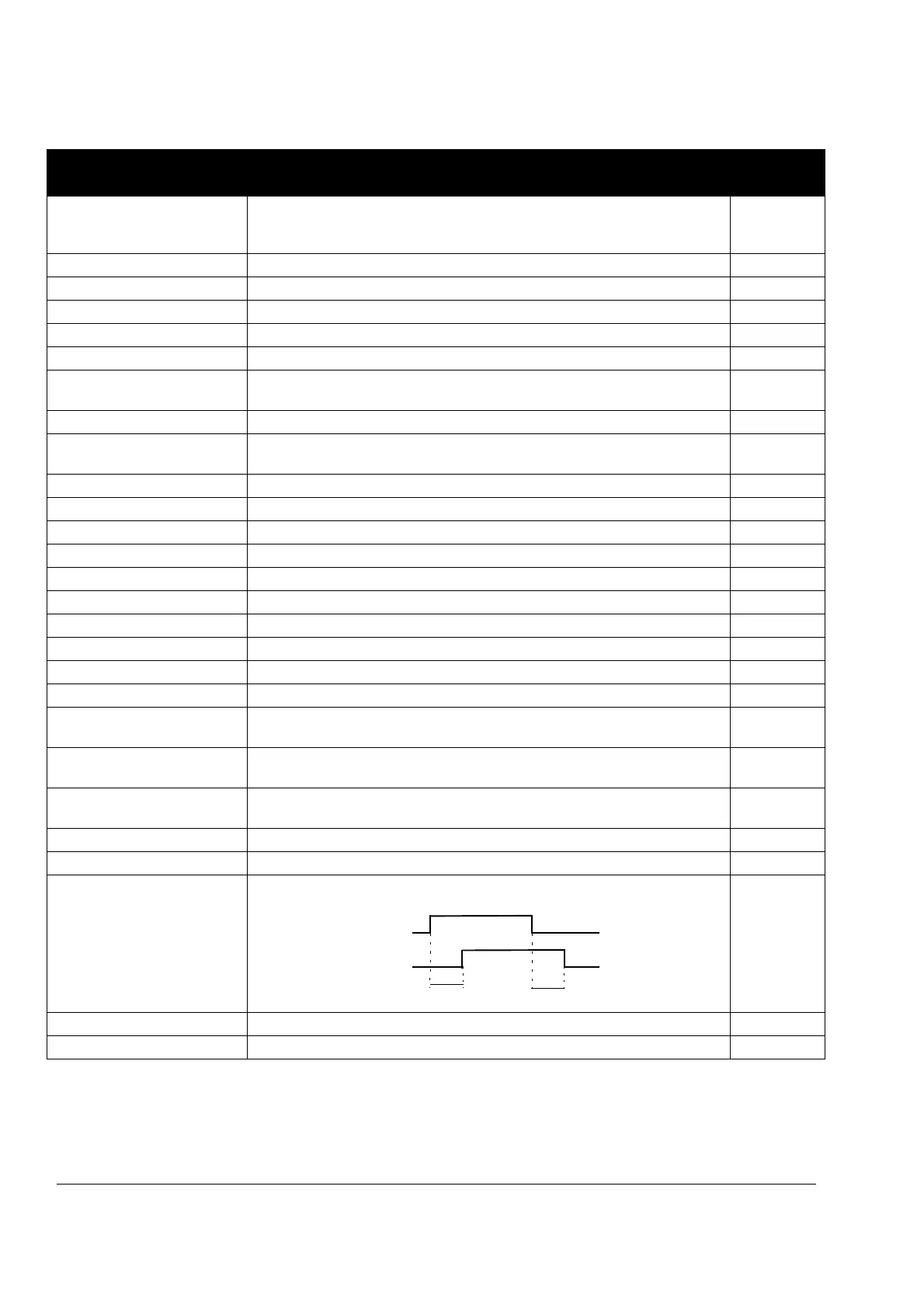
1404 RO1 ON DELAY Defines the operation delay for relay output RO. 0
0.0…3600.0 s Delay time. The figure below illustrates the operation (on) and release (off)
delays for relay output RO.
1405 RO1 OFF DELAY Defines the release delay for relay output RO. 0
0.0…3600.0 s Delay time. See the figure for parameter 1404 RO1 ON DELAY.
Parameters in the Long Parameter mode
Index Name/Selection Description Def
1404 ON DELAY
1405 OFF DELAY
Control event
Relay status