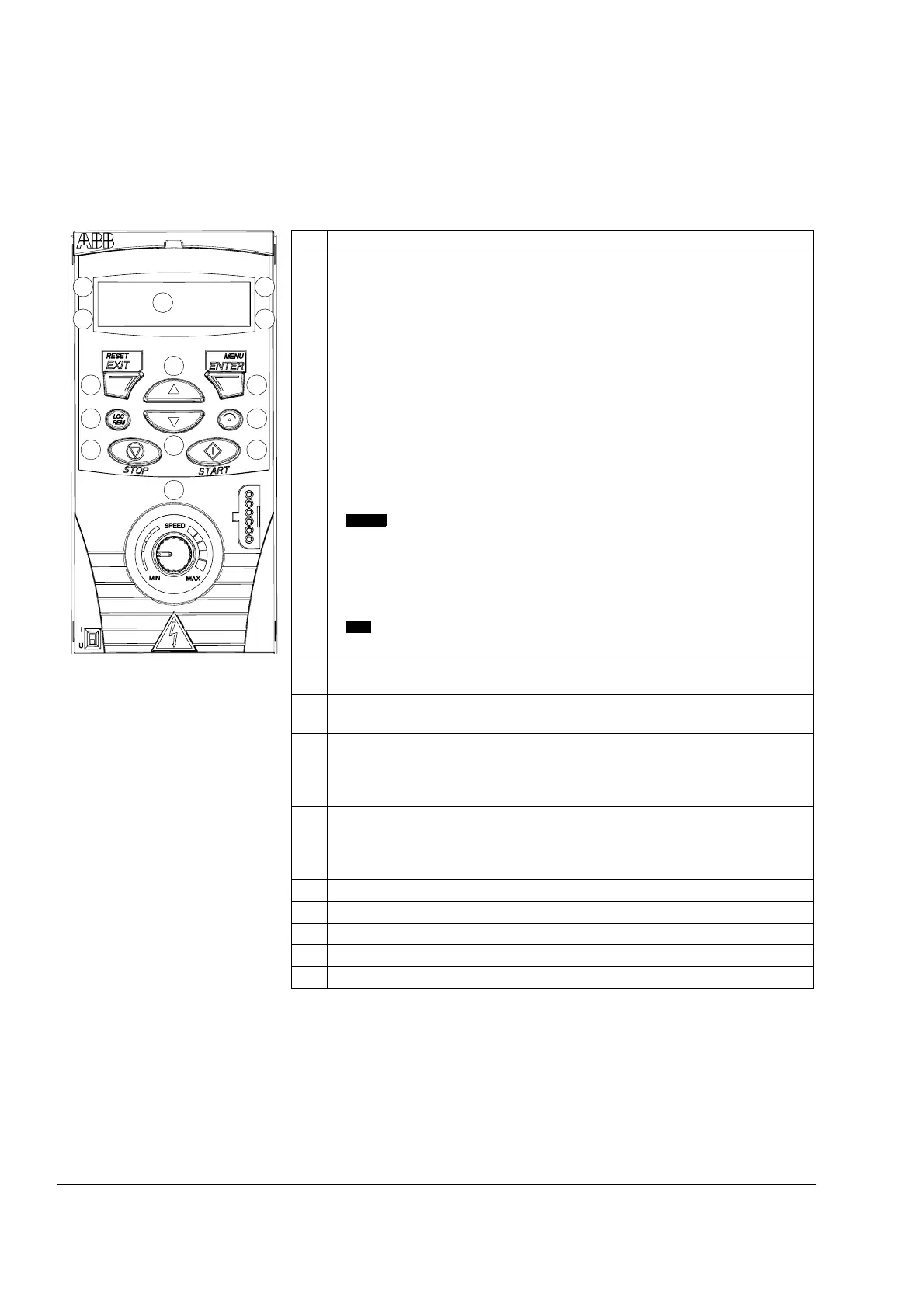
Control panel
46
Overview
The following table summarizes the key functions and displays on the Integrated
Control Panel.
No. Use
1 LCD display – Divided into five areas:
a. Upper left – Control location:
LOC: drive control is local, that is, from the control panel
REM: drive control is remote, such as the drive I/O.
b. Upper right – Unit of the displayed value.
s: Short Parameter mode, browsing the list of parameters.
c. Center – Variable; in general, shows parameter and signal values, menus or
lists. Also displays alarm and fault codes.
d. Lower left and center – Panel operation state:
OUTPUT: Output mode
PAR:
Steady: Parameter modes
Flashing: Changed Parameters mode
MENU: Main menu.
: Fault mode.
e. Lower right – Indicators:
FWD (forward) / REV (reverse): direction of the motor rotation
Flashing slowly: stopped
Flashing quickly: running, not at setpoint
Steady: running, at setpoint
: Displayed value can be modified (in the Parameter or Reference
mode).
2 RESET/EXIT – Exits to the next higher menu level without saving changed
values. Resets faults in the Output and Fault modes.
3 MENU/ENTER – Enters deeper into menu level. In the Parameter mode,
saves the displayed value as the new setting.
4Up –
• Scrolls up through a menu or list.
• Increases a value if a parameter is selected.
Holding the key down changes the value faster.
5 Down –
• Scrolls down through a menu or list.
• Decreases a value if a parameter is selected.
Holding the key down changes the value faster.
6 LOC/REM – Changes between local and remote control of the drive.
7 DIR – Changes the direction of the motor rotation.
8 STOP – Stops the drive in local control.
9 START – Starts the drive in local control.
10 Potentiometer – Changes the frequency reference.
FAULT
SET
LOC
OUTPUT FWD
A
1.1
1a
2 3
4
5
6 7
8 9
1c
1d
1b
1e
10