Technical data
126
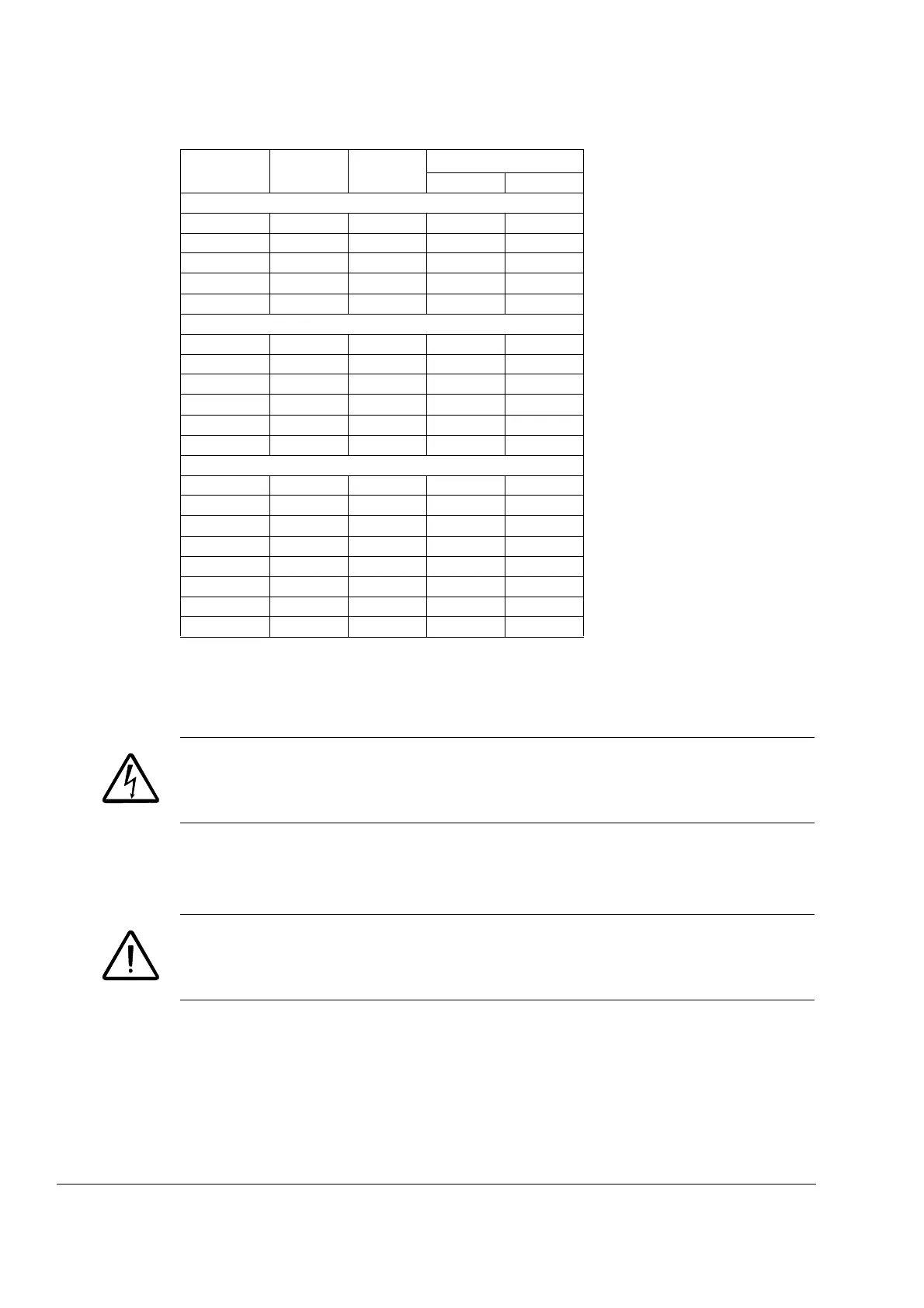
R
min
= minimum allowed brake resistor
R
max
= maximum allowed brake resistor
P
BRmax
= maximum braking capacity of the drive, must exceed the desired braking power.
WARNING! Never use a brake resistor with a resistance below the minimum value
specified for the particular drive. The drive and the internal chopper are not able to
handle the overcurrent caused by the low resistance.
Resistor installation and wiring
All resistors must be installed in a place where they will cool.
WARNING! The materials near the brake resistor must be non-flammable. The
surface temperature of the resistor is high. Air flowing from the resistor is of
hundreds of degrees Celsius. Protect the resistor against contact.
Use a shielded cable with the same conductor size as for drive input cabling (see
section Power cables: terminal sizes, maximum cable diameters and tightening
torques on page 118). For short-circuit protection of the brake resistor connection,
see Brake resistor connection on page 120. Alternatively, a two-conductor shielded
cable with the same cross-sectional area can be used. The maximum length of the
resistor cable(s) is 5 m (16 ft). For the connections, see the power connection
diagram of the drive on page 32.
Type R
min
R
max
P
BRmax
ACS150- ohm ohm kW HP
1-phase U
N
= 200…240 V (200, 208, 220, 230, 240 V)
01x-02A4-2 70 390 0.37 0.5
01x-04A7-2 40 200 0.75 1
01x-06A7-2 40 130 1.1 1.5
01x-07A5-2 30 100 1.5 2
01x-09A8-2 30 70 2.2 3
3-phase U
N
= 200…240 V (200, 208, 220, 230, 240 V)
03x-02A4-2 70 390 0.37 0.5
03x-03A5-2 70 260 0.55 0.75
03x-04A7-2 40 200 0.75 1
03x-06A7-2 40 130 1.1 1.5
03x-07A5-2 30 100 1.5 2
03x-09A8-2 30 70 2.2 3
3-phase U
N
= 380…480 V (380, 400, 415, 440, 460, 480 V)
03x-01A2-4 200 1180 0.37 0.5
03x-01A9-4 175 800 0.55 0.75
03x-02A4-4 165 590 0.75 1
03x-03A3-4 150 400 1.1 1.5
03x-04A1-4 130 300 1.5 2
03x-05A6-4 100 200 2.2 3
03x-07A3-4 70 150 3.0 3
03x-08A8-4 70 110 4.0 5
00353783.xls E