104 Control macros
Terminal sizes
• (frames R0…R8): 0.14…1.5 mm
2
(all terminals)
• Tightening torques: 0.5…0.6 N·m (0.4 lbf·ft)
Notes
1)
Current [0(4)…20 mA, R
in
< 500 ohm] or voltage [ 0(2)…10 V, R
in
> 200 kohm]
input as selected with parameter 12.15 AI1 unit selection.
2)
Current [0(4)…20 mA, R
in
= 100 ohm] or voltage [ 0(2)…10 V, R
in
> 200 kohm]
input as selected with parameter 12.25 AI2 unit selection.
3)
Total load capacity of the auxiliary voltage output +24V (X2:10) =
6.0 W (250 mA / 24 V) - User can use this source for either of the I/O connections
(DI1... DI2- RO1 or DI3...DI6 - RO2
~RO3).
4)
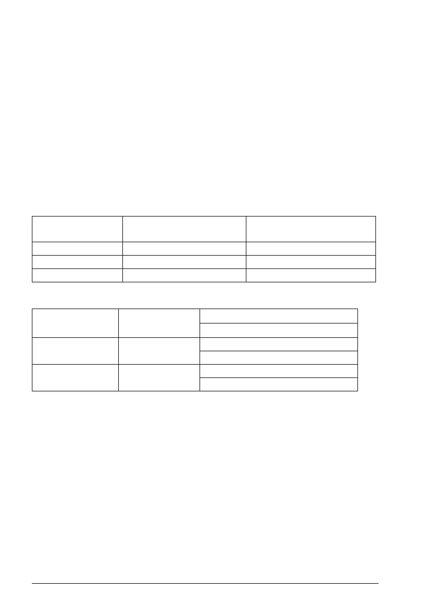
The constant speed are set based on the combination of sources as follows:
5)
The speed reference ramp is set based on the combination of sources as follows:
6
Connected with jumpers at the factory.
7)
Applicable for R0...R2 frames only.
8)
Use shielded twisted-pair cables for digital signals.
9)
Ground the outer shield of the cable 360 degrees under the grounding clamp on
the grounding shelf for the control cables.
10)
Input signal
11)
Output signal
For information on cable connection and drive operation, see Control Connections in
the hardware manual (3AXD50000044998).
Source defined by
parameter 28.22
Source defined by
parameter 28.23
Constant speed active
0 0 Set speed through AI1
10 Constant frequency 1
01 Constant frequency 2
DI5
parameter 28.71
Ramp set
Parameters
Scalar control (default)
0 Acc/Dec time 1 28.72 Freq acceleration time 1
28.73 Freq deceleration time 1
1 Acc/Dec time 2 28.74 Freq acceleration time 2
28.75 Freq acceleration time 2