44 Program features
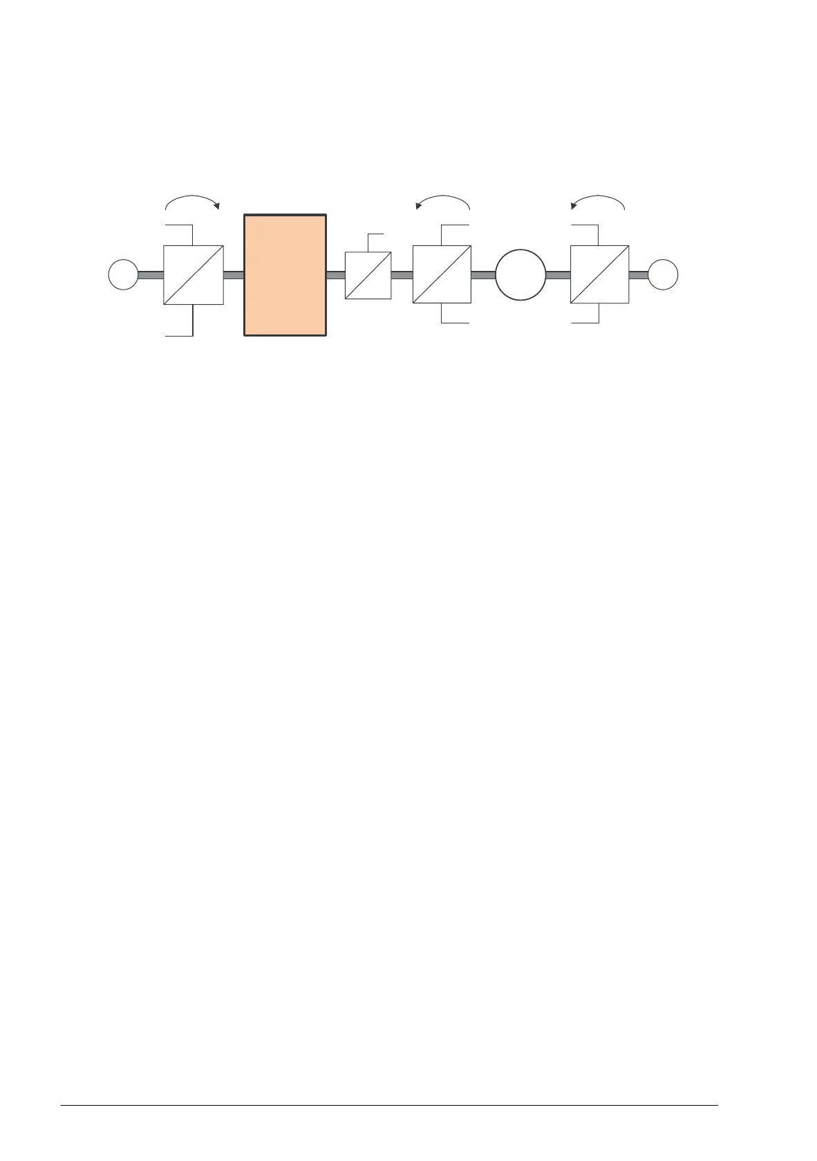
Any mechanical gear ratios between the components (motor, motor encoder, load,
load encoder) are specified using the gear parameters shown in the diagram below.
Any gear ratio between the load encoder and the load is defined by 90.53 Load gear
numerator and 90.54 Load gear denominator. Similarly, any gear ratio between the
motor encoder and the motor is defined by 90.43 Motor gear numerator and
90.44 Motor gear denominator. In case the internal estimated position is chosen as
load feedback, the gear ratio between the motor and load can be defined by
90.61 Gear numerator and 90.62 Gear denominator. By default, all of the ratios
mentioned above are 1:1. The ratios can only be changed with the drive stopped;
new settings require validation by 91.10 Encoder parameter refresh.
Position counter
The control program contains a position counter feature that can be used to indicate
the position of the load. The output of the counter function, parameter 90.07 Load
position scaled int, indicates the scaled number of revolutions read from the selected
source (see section Load and motor feedback on page 43).
The relation between revolutions of the motor shaft and the translatory movement of
the load (in any given unit of distance) is defined by parameters 90.63 Feed constant
numerator and 90.64 Feed constant denominator. This gear function can be changed
without the need of a parameter refresh or position counter reinitialization – however,
the counter output is only updated after new position input data is received.
For detailed parameter connections of the load feedback function, see the block
diagram on page 424.
Load encoder to load
scaling
Load encoder
Load
90.4390.53
90.44
90.54
90.62
90.61
M
Motor
encoder
Motor to load
scaling
Motor encoder to motor
scaling
ee