7-B-2 Chapter 7: Gas Analyzer Configuration 42/24-10 EN Rev. 9
Standard Configuration
Standard
Configuration
Various applications are factory-configured. These standard configurations are
based on
• Standard input/output pin configuration
• The available sample components
Some factory-configured applications require field linking of additional function
blocks.
Example:
Limit Value
Monitoring
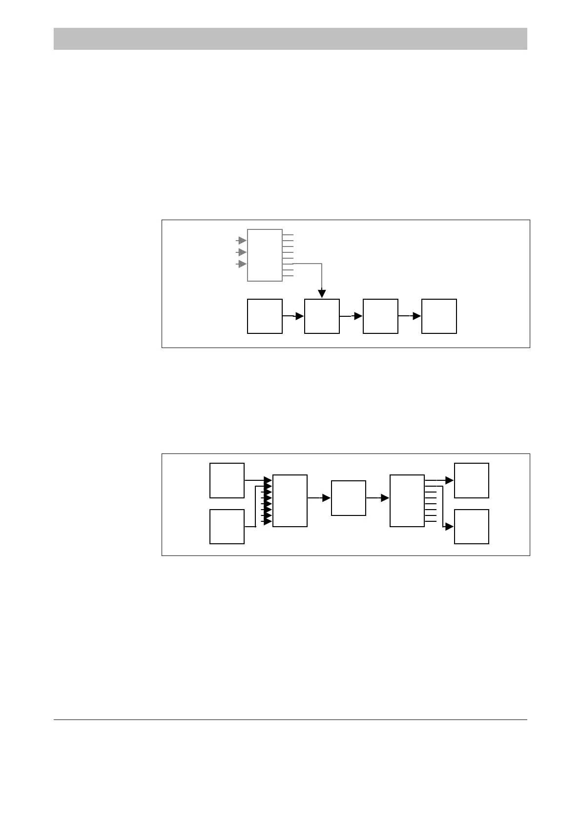
The limit value monitoring application (see Figure 7-B-1) consists of a factory-
configured link between the Component measurement value, Hold, Limit
monitor and Digital output function blocks.
Figure 7-B-1
Limit
monitor
‘Alarm CO’
Comp.
meas.
value
‘CO’
Digital
output
‘Alarm CO’
Hold
‘Alarm CO’
Autocal
‘’
Example:
Measurement Range
Switching/Feedback
The measurement range switching/feedback application (see Figure 7-B-2)
consists of a factory-configured linkage between
• A Range control function block with several Digital input function blocks and a
Component range function block, as well as
• a Range feedback function block with the Component range function block
and several Digital output function blocks.
Figure 7-B-2
Range
control
‘’
Range
feedback
‘’
Digital
output
‘’
Comp.
range
‘’
Digital
input
‘’
Digital
input
‘’
Digital
output
‘’

 Loading...


