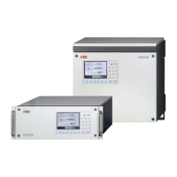
ii AO2000 Series Operator’s Manual 42/24-10 EN Rev. 9
Table of Contents
Page
Preface viii
Relationship between Operator’s Manual and Software Version x
Important Safety Information xi
Safety Tips for Handling Electronic Measurement Devices xii
Explosion-protected Version with Type of Protection II 3G
for Measurement of Non-flammable Gases and Vapors:
Description and Special Conditions for Operation xiii
Chapter 1 Preparing the Installation
Installation Location Requirements 1-1
Sample Gas Inlet and Outlet Conditions 1-3
Test Gases for Calibration 1-5
Purge Gas for Housing Purge 1-6
Power Supply Information 1-7
Power Supply 1-8
Scope of Delivery 1-9
Material Needed for Installation (not delivered) 1-10
List of Figures Related to Installation 1-11
Guideline for Installation and Start-Up 1-12
Chapter 2 Gas Analyzer Unpacking and Installation
Gas Analyzer Unpacking 2-1
Gas Analyzer Identification 2-2
Dimensional Diagrams 2-4
Gas Connections Installation 2-5
Gas Analyzer Installation 2-6
Chapter 3 Gas Line Connection
Magnos206: Gas Connections 3-1
Magnos27: Gas Connections 3-2
Magnos27: Gas Connections (Sample Cell Direct Connection) 3-3
Caldos25, Caldos27: Gas Connections 3-4
Caldos25: Gas Connections
(Corrosive Sample Gas or Flowing Reference Gas) 3-5
Limas11: Gas Connections
(Standard Cell, Quartz Cell, Quartz Cell with Center Connection) 3-6
Limas11: Gas Connections (Quartz Cell with PFA Tubes) 3-7
Limas11: Gas Connections (Safety Cell) 3-8
Uras26: Gas Connections 3-9
Gas Diagrams 3-10
Pressure Sensor 3-11
Housing Purge 3-12
Gas Line Connection 3-13
Continued on next page

 Loading...