2-4 Chapter 2: Gas Analyzer Unpacking and Installation 42/24-10 EN Rev. 9
Dimensional Diagrams
Figure 2-2
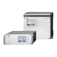
19-Inch Housing
(dimensions in mm)
Error Mai nt Power
483
1
7
7
413
5
563
597
Figure 2-3
Wall-Mount Housing
(dimensions in mm)
Error Maint
Power
Additional Notes • The connection box shown with dashed lines in the dimensional diagrams is
flange-mounted to the IP-54 housing.
• Observe the installation location requirements (see Page 1-1).
• The connecting lines require additional installation clearance (approx. 100 mm).
• When installing the wall-mount housing note that clearance (approx. 60 mm) is
required on the left side to allow the door to swing open.
• The 19-inch housing and the wall-mount housing should be installed with
vertical orientation of the display.
• Multiple system housings in a 19-inch rack should be installed with a separation
of at least one height unit.

 Loading...