Mounting
30 FEX300, FEX500 OI/FEX300/FEX500-EN
Change from one to two colu mns
4.5 Installation Requirements
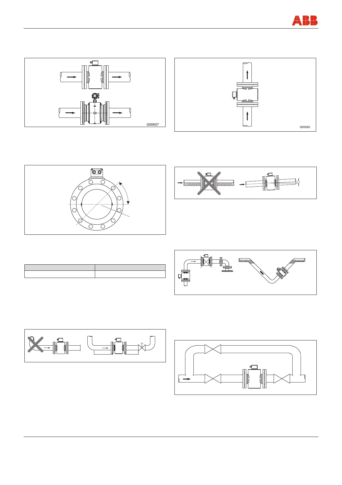
The device measures the flowrate in both directions. Forward flow is
the factory setting, as shown in Fig. 13.
Fig. 13
4.5.1 Electrode axis
Electrode axis (1) should be horizontal if at all possible or no more
that 45° from horizontal.
G00041
max. 45°
1
Fig. 14
4.5.2 In- and outlet pipe sections
Straight inlet section Straight outlet section
3 x DN 2 x DN
DN = Flowmeter sensor size
• Do not install fittings, manifolds, valves etc. directly in front of the
meter tube (1).
• Butterfly valves must be installed so that the valve plate does not
extend into the flowmeter sensor.
• Valves or other turn-off components should be installed in the
outlet pipe section (2).
• For compliance with the measuring accuracy, observe the inlet
and outlet pipe sections.
G00037
1
2
3xDN
2xDN
Fig. 15
4.5.3 Vertical connections
• Vertical installation for measurement of abrasive fluids, flow
preferably from below to above.
Fig. 16
4.5.4 Horizontal connections
• Meter tube must always be completely full.
• Provide for a slight incline of the connection for degassing.
G00038
3°
Fig. 17
4.5.5 Free inlet or outlet
• Do not install the flowmeter at the highest point or in the draining-
off side of the pipeline, flowmeter runs empty, air bubbles can
form (1).
• Provide for a siphon fluid intake for free inlets or outlets so that
the pipeline is always full (2).
G00040
1
2
Fig. 18
4.5.6 Strongly contaminated fluids
• For strongly contaminated fluids, a bypass connection according
to the figure is recommended so that operation of the system can
continue to run without interruption the during the mechanical
cleaning.
G00042
Fig. 19