Electrical connections
OI/FEX300/FEX500-EN FEX300, FEX500 45
5.3 Connecting the transmitter
Important (Notice)
An additional document with Ex safety instructions is available for measuring systems that are
used in explosion hazardous areas. As a result, it is crucial that the specifications and data it
lists are also observed.
5.3.1 Connecting the supply power
The line voltage and power consumption are indicated on the name plate for the transmitter.
A circuit breaker with a maximum rated current of 10 A must be installed in the supply power
line of the transmitter.
The wire cross-sectional area of the supply power cable and the circuit breaker used must
comply with VDE 0100 and must be dimensioned in accordance with the current consumption of
the flowmeter measuring system. The leads must comply with IEC 227 and/or IEC 245.
The circuit breaker should be located near the transmitter and marked as being associated with
the device.
The supply power is connected to terminal L (phase), N (neutral), or 1+, 2-, and PE, as stated
on the name plate.
Connect the transmitter and flowmeter sensor to functional ground.
Important (Notice)
• Observe the limit values for the supply power provided in chapter 12.3.1 "Electrical
proper
ties".
• Observe the voltage drop for large cable lengths and small cable cross-sections. The
voltage at the terminals of the device may not fall below the minimum value required.
• Complete the electrical connection according to the connection diagram.
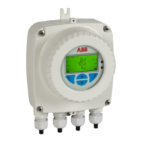
The terminals for the supply power can be found under the terminal cover (1).
Fig. 40
1 Terminal cover
 Loading...


