Commissioning
OI/FEX300/FEX500-EN FEX300, FEX500 55
G00679-01
1
234AB
3
A
B
4
1
5
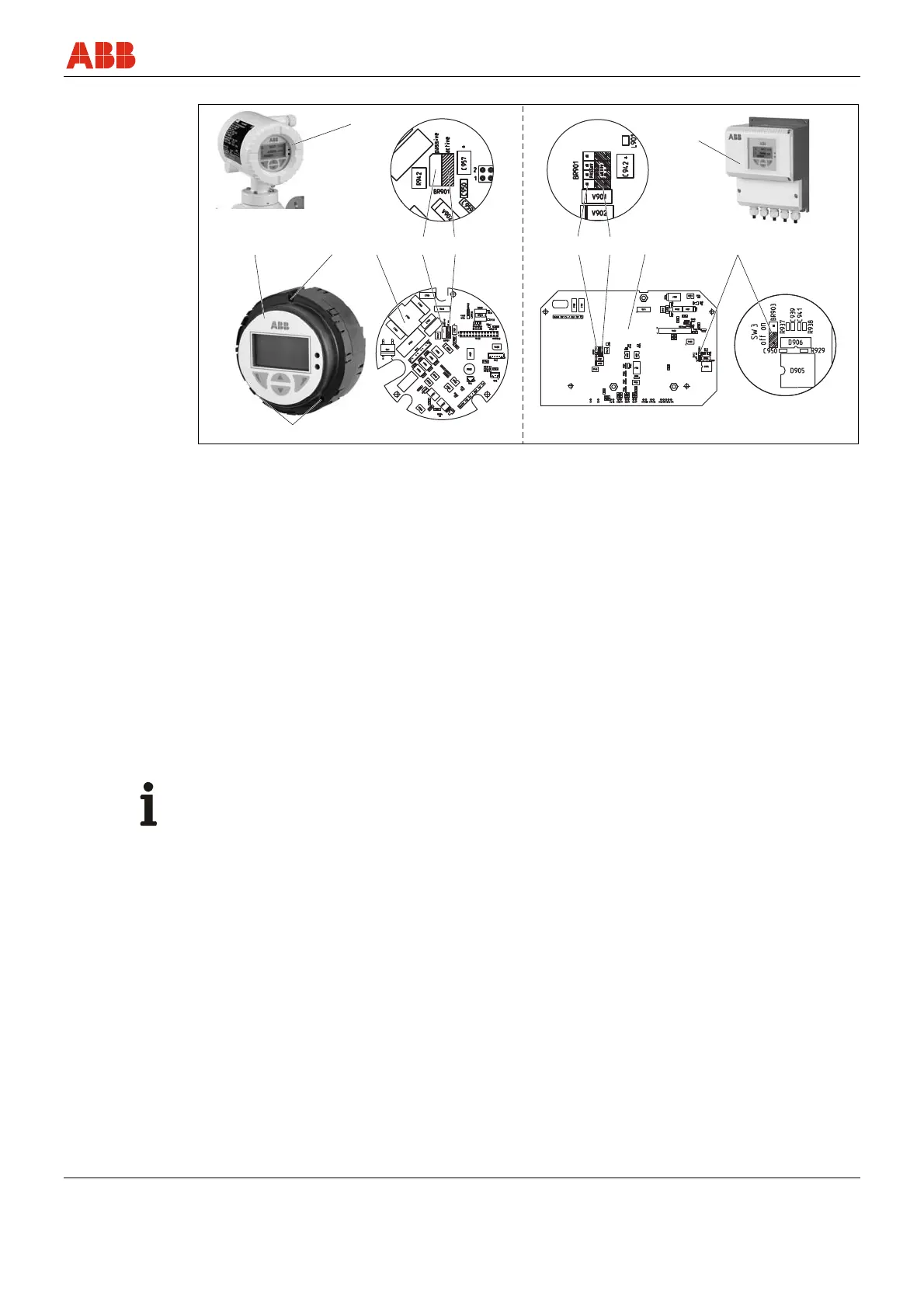
Fig. 54
1 Housing cover
2 Transmitter electronics unit
3 Mounting screws for the transmitter
electronics unit
4 Backplane (in the transmitter housing)
5 Jumper SW3
• off: SensorMemory provided in the
flowmeter sensor (standard)
• on: No SensorMemory in flowmeter
sensor
Set the current output as follows:
1. Switch off the supply power.
2. Open the housing cover.
3. Remove the mounting screws for the transmitter electronics unit
4. Pull out the transmitter electronics unit
5. Plug in the jumper on the backplane in the transmitter housing to Position A or B.
• A = 4 ... 20 mA output, passive
• B = 4 ... 20 mA output, active
Important (Notice)
The backplane is not installed in the transmitter electronic unit (3) but rather in the transmitter
housing (1).
6. Reinstall the transmitter electronic unit in reverse order