2 Installation and commissioning
2.6.5. Installation of position switches (option)
1233HAC022033-001 Revision: K
© Copyright 2004-2011 ABB. All rights reserved.
Axis 1
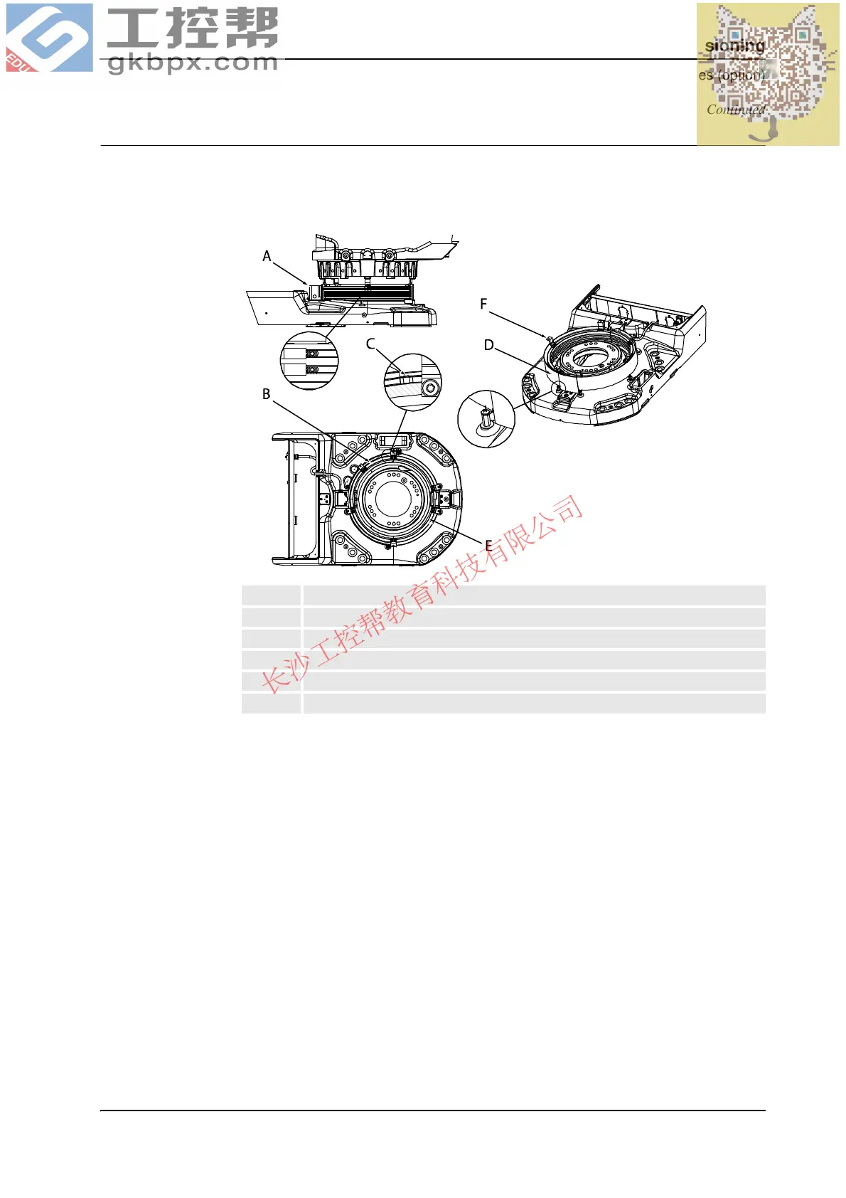
The illustration below shows the position switch for axis 1. There is no extra cabling installed
on the robot, as for axes 2 and 3. Instead the switch is connected directly to the connector in
the base, R1.SW1.
xx0100000158
A Position switch, axis 1
B Cam
C Set screw, cam (cam stop)
D Protection sheet
E Rail
F Rail attachment
Continued
Continues on next page
 Loading...


