4 Repair
4.6.2. Replacement of motor axis 2
3373HAC022033-001 Revision: K
© Copyright 2004-2011 ABB. All rights reserved.
6.
CAUTION!
The motor weighs 32 kg! All lifting equipment
used must be sized accordingly!
7. Lift the motor and guide it onto the guide pins,
as close to the correct position as possible
without pushing the motor pinion into the
gear.
Make sure that the motor is turned the right
direction, that is the cables facing
downwards.
8. Remove the lifting tool and allow the motor to
rest on the guide pins.
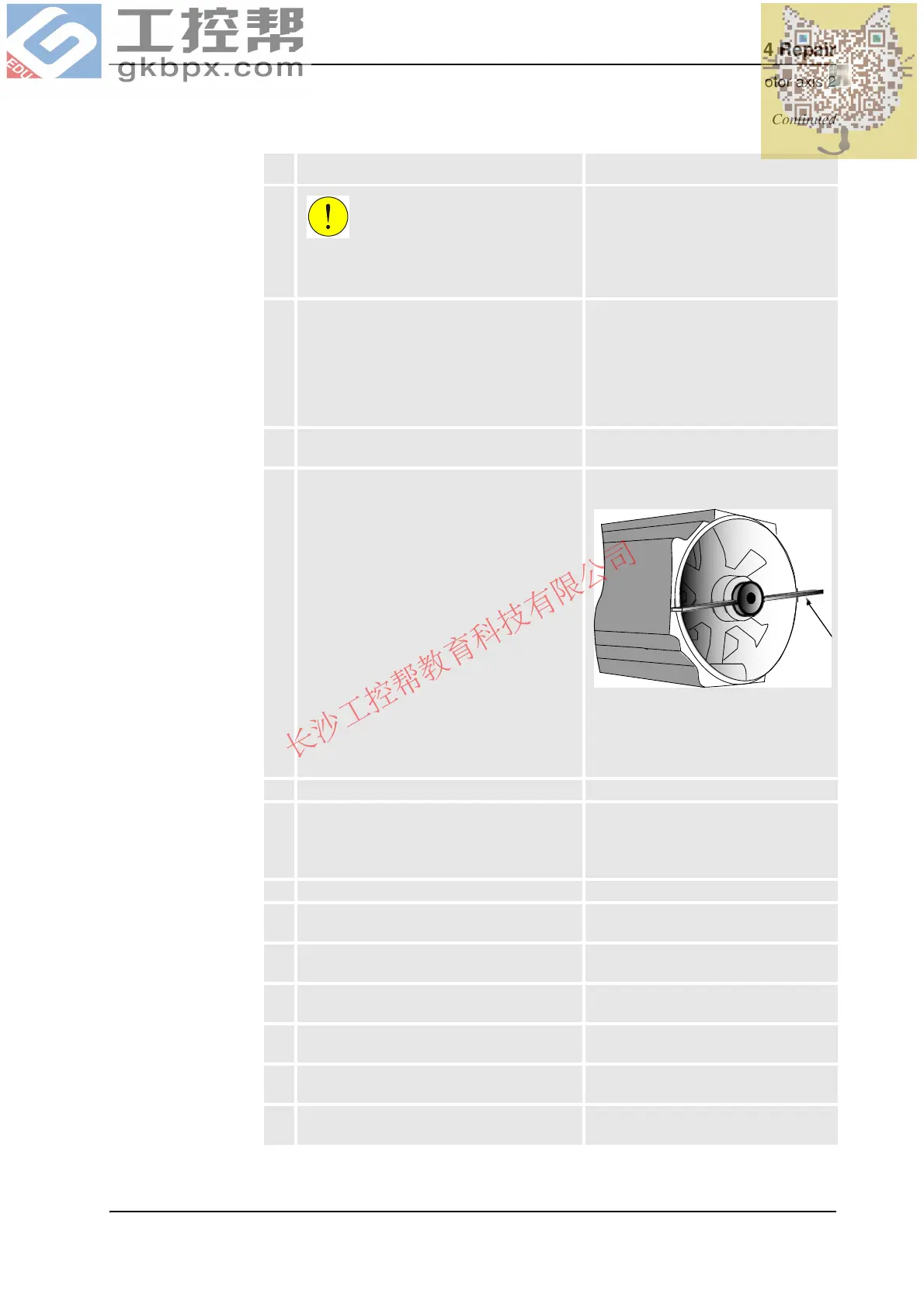
9. Use the rotation tool in order to rotate the
motor pinion when mating it to the gear (see
the figure to the right). Fit the motor, making
sure the motor pinion is properly mated to the
gear of gearbox axis 2 and that it does not get
damaged.
Art. no. is specified in Required
equipment on page 333.
xx0200000165
The rotation tool is used beneath the
motor cover, directly on the motor shaft
as shown in the figure above.
• A: Rotation tool
10. Remove the guide pins.
11. Secure the motor with four attachment screws
and plain washers.
If required, use the extension 300mm for bits
1/2".
M10 x 40, tightening torque: 50 Nm.
Reused screws may be used, providing
they are lubricated as detailed in section
Screw joints on page 423 before fitting.
12. Disconnect the brake release voltage.
13. Reconnect all connectors beneath the motor
cover.
Connect in accordance with markings
on connectors.
14. Refit the cable gland cover at the cable exit
with its two attachment screws.
Shown in the figure Location of motor on
page 333.
15. Refit the cover on top of the motor with its four
attachment screws.
Make sure the cover is tightly sealed!
16. Remove the lock screw from the hole for lock
screw.
Shown in the figure Location of motor on
page 333.
17. Perform a leak down test. Detailed in Performing a leak-down test
on page 246.
18. Refill the gearbox with oil. Detailed in the section Oil change,
gearbox axis 2 on page 203.
Action Note
Continued
Continues on next page