ScreenMaster RVG200
Paperless recorder 3 Installation
OI/RVG200-EN 17
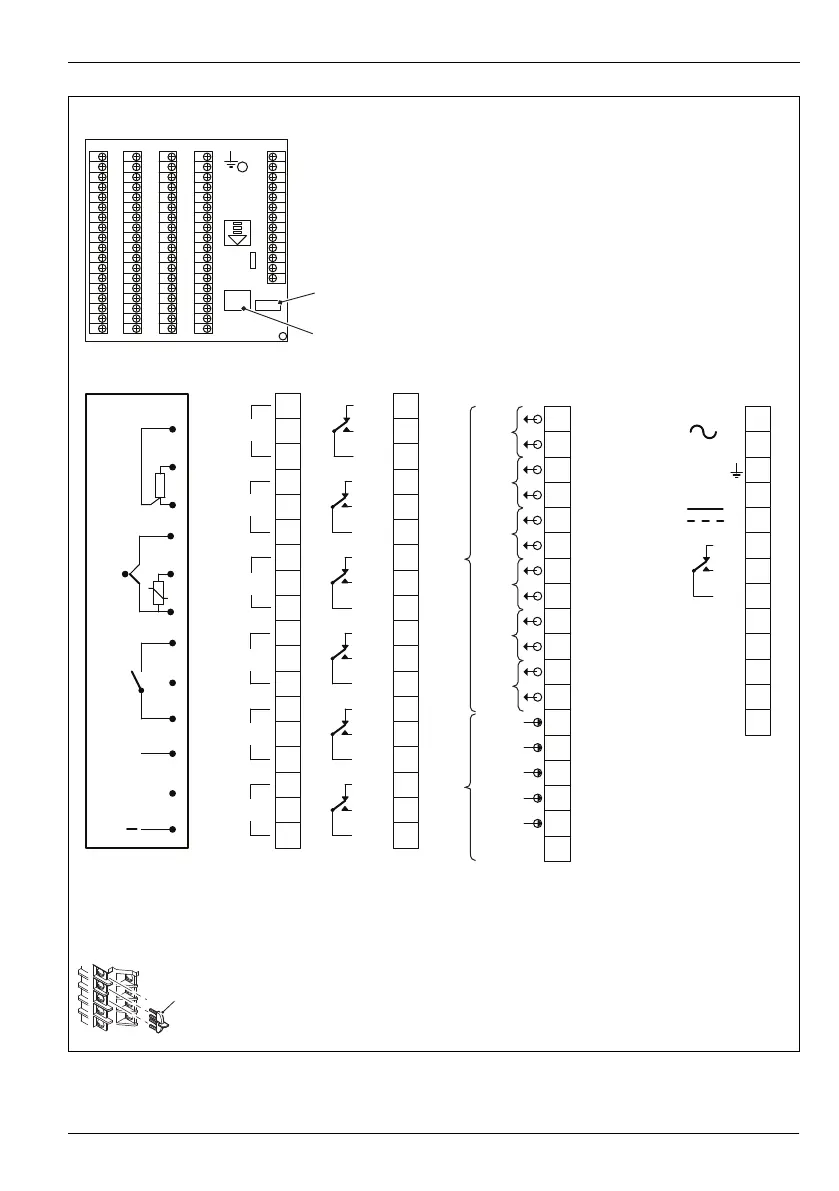
* Each thermocouple input must have either a cold junction assembly (part number CM30/0052) or
shorting link (part number RVG200/0118) fitted. Each analog input card with a thermocouple input must
have a minimum of 1 cold junction assembly fitted. For applications requiring maximum thermocouple
accuracy, it is recommended that each thermocouple input is fitted with a cold junction assembly.
Fig. 3.6 Electrical connections
3
11
10
9
8
7
6
5
4
1
2
18
17
16
15
14
13
12
3
11
10
9
8
7
6
5
4
1
2
18
17
16
15
14
13
12
3
11
10
9
8
7
6
5
4
1
2
13
12
L
N
+
–
Tx +
Tx –
Tx / Rx
+
–
3
11
10
9
8
7
6
5
4
1
2
18
17
16
15
14
13
12
+
*
AEDCB
Tx / Rx
1
2
3
4
5
6
1+
2+
3+
4+
5+
Analog or digital outputs
Tx PSU
Digital inputs
Inputs 1 to 6
Communications common
A, B, C, D
Analog Input
Input 1
RTD
R
Module positions
A, B, C, D
Relay
C, D
Hybrid
Input 2
Input 3
Input 4
Input 5
Input 6
THC
Volt-free
digital input
mV, V, mA,
digital input (V)
Common
N/C
N/O
C
RJ45
USB
N/C
N/O
C
N/C
N/O
C
N/C
N/O
C
N/C
N/O
C
N/C
N/O
C
E
Power supply
MODBUS (if fitted)
100 to
240VAC
24VDC
Common earth (ground)
Cold junction