20 ZX2 GAS-INSULATED MEDIUM VOLTAGE SWITCHGEAR
—
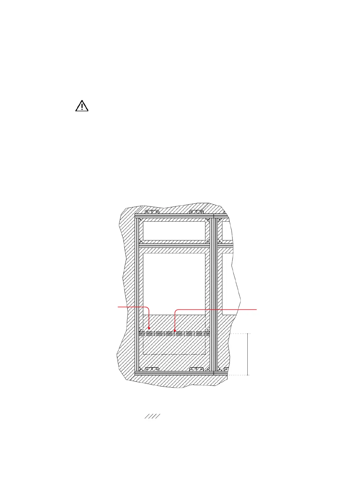
Fig. 3.2.1.1.2:
Plan view of standard
foundation frame:
Embedding of the
foundation frame
in floor topping.
: Topping material
Additional supporting beam
(only required when voltage
transformers are fitted
in the cable termination
compartment and the floor
Front of switchgear
cable opening
420
• Align the foundation frame vertically as
described above and fasten it to the floor as
mentioned above.
• Install the following foundation frames in the
same way.
• Ground the completely assembled frame.
Further details on this can be found in the order
documents.
Important note
When applying the floor topping,
carefully fill under the foundation frame
with topping material.
Fill in the marked area in fig. 3.2.1.1.2
with topping material.
(Details on the height of the finished
floor can be found in fig. 3.2.1.1.1,
When voltage transformers are used in the cable
termination compartment, the panel floor plate
needs to be supported. That support is ensured
by complete backfilling with topping material in
the marked area in fig. 3.2.1.1.2. If the floor plate
is not supported by topping material at the rear
of the cable termination compartment (e.g. in the
case of cable openings elongated to the rear), an
additional structural beam is required. The
position of that beam can be found in fig.
3.2.1.1.2.