3. INSTALLATION OF THE SWITCHGEAR AT SITE 31
Important note
Apply drawing or pressing tools to a
large area on the panel directly above the
floor (for instance by using a wooden
as to avoid damage to the panel.
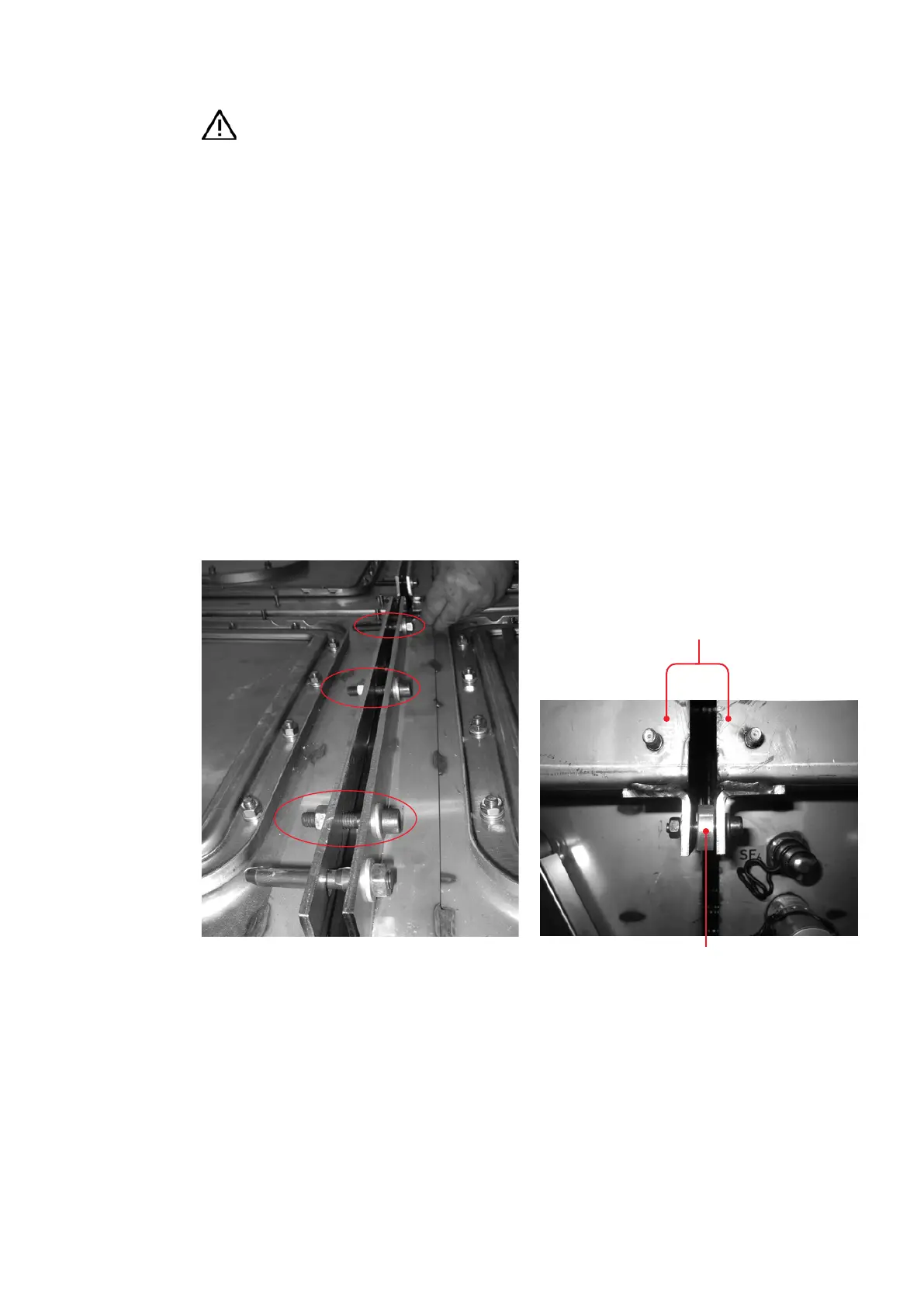
• As soon as the distance between the two panels
is appropriately small, connect the fastening
brackets of two adjacent busbar compartments
with three M 10 x 50 cheese head screws (per
busbar compartment), dished washers and nuts
(fig. 3.3.2.6). Initially, only lightly tighten the bolt
connection.
• Connect the brackets on the adjacent busbar
compartments with one M 8 x 40 cheese head
screw, nut and washers for each connecting
point (fig. 3.3.2.7). A spacer is used to bridge
the distance between the two brackets
(fig. 3.3.2.8). In the case of the rear busbar com-
partment with the cover removed, the brackets
are accessible from the rear, and in the case of
the front busbar compartment they are accessi-
ble from the front when the low voltage com-
partment is open. Initially, only lightly tighten
the bolt connection.
• Connect the two panels together by tightening
the screws across the diagonal at the points
marked in fig. 3.3.2.9 - 12. Fully tighten the
bolted connections shown in fig. 3.3.2.7 and
3.3.2.8 across the diagonal.
• Check the alignment of the panel and fasten it
to the foundation frame rails as described
above.
—
Fig. 3.3.2.7:
Bolting the pan-
els together
—
Fig. 3.3.2.8:
Bolting the panels
together
(view of the busbar com-
partment from the rear)
Busbar compartments
Spacer
—
Fig. 3.3.2.7
—
Fig. 3.3.2.8