3. INSTALLATION OF THE SWITCHGEAR AT SITE 47
pins to the stud bolts on the enclosure (tighten-
ing torque 9.2 ft·lbf) as shown in fig. 3.3.7.3.1.
• Slowly and carefully insert the transformer into
the socket. The plug-in connection must slide
easily into the corresponding socket. Check the
position of the silicone parts in relation to the
socket continuously and correct if necessary.
A counter-pressure will become noticeable ap-
prox. 0.8 in before the limit position is reached.
• Initially, only fasten the voltage transformer
with screws at the points marked in fig. 3.3.7.3.2.
Install the further voltage transformers in the
same way.
Voltage transformers for operating voltages
> 24 kV
Important note
Ground the threaded bores in the voltage
transformer sockets by fitting them with
countersunk screws, DIN 7991, M 8 x 30
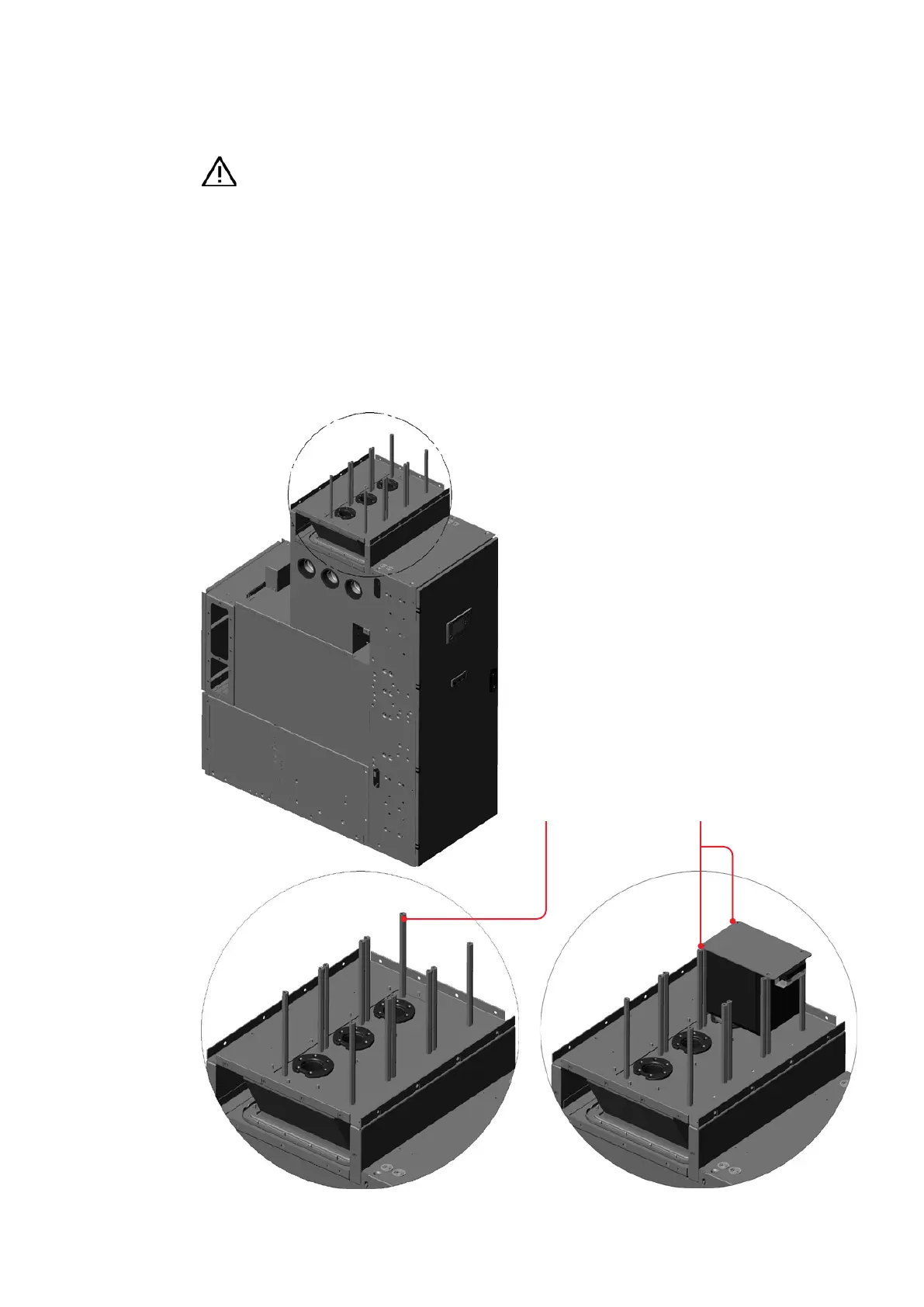
• In the case of systems with an operating volt-
age > 24 kV, hexagonal pins are used to fasten
the voltage transformers. Screw the hexagonal
—
Fig. 3.3.7.3.1:
Hexagonal pins for
fastening of the
voltage transformer
—
Fig. 3.3.7.3.2:
Fastening of the
voltage transformer,
version for operating
voltage > 24 kV
2 x cheese head screw, M 10 x 25 DIN 912
2 x dished washer, 10 DIN 6796Hexagonal pin
—
Fig. 3.3.7.3.1
—
Fig. 3.3.7.3.2
A
Detail A