48 ZX2 GAS-INSULATED MEDIUM VOLTAGE SWITCHGEAR
Voltage transformers for operating voltages up
to 24 kV
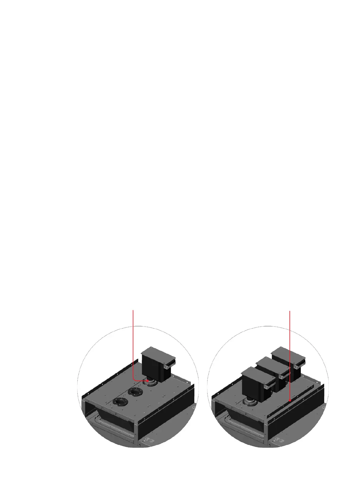
• Remove the three grounding screws (fig.
3.3.7.2.1) on the flange of the voltage trans-
former socket, if fitted.
• Slowly and carefully insert the transformer into
the socket. The plug-in connection must slide
easily into the corresponding socket. Check the
position of the silicone parts in relation to the
socket continuously and correct if necessary. A
counter-pressure will become noticeable ap-
prox. 0.8 in before the limit position is reached.
• Screw the flange of the voltage transformer to
the voltage transformer socket (see fig. 3.7.3.3)
in the panel, tightening the screws across the
diagonal.
• Mount the other voltage transformers as de-
scribed.
The further installation procedure is identical
for both types of voltage transformer.
• Wipe any surplus grease off from the area of the
voltage transformer flange above the voltage
transformer’s plug-in connection as far as pos-
sible.
• Screw the fastening bracket to the roof plate of
the plenum as shown in fig. 3.3.7.3.4.
—
Fig. 3.3.7.3.3:
Fastening of the
voltage transformer,
version for operating
voltage up to 24 kV
—
Fig. 3.3.7.3.3
—
Fig. 3.3.7.3.4
3 x cheese head screw M 8 x 40 DIN 912
3 x washer 8,4 DIN 433
3 x spring washer A8 DIN 127
Fastening bracket
3 x cheese head screw M 8 x 20 DIN 912
3 x dished washer 8 DIN 6796
—
Fig. 3.3.7.3.4:
Fitting the fas-
tening bracket