3. INSTALLATION OF THE SWITCHGEAR AT SITE 49
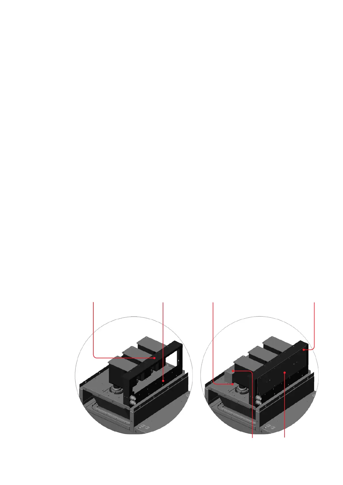
• Fasten the transformer cover to the previously
fitted fastening bracket and to the top plates of
the voltage transformers (fig. 3.3.7.3.5).
• Lead the transformer wiring through the gland
in the transformer cover.
• Wire the transformers as set out in section
3.3.7.9.
• If required, wire and mount the damping resis-
tor according to fig. 3.3.7.3.6 and chapter 3.3.7.7.
• Fit the cover plate (fig. 3.3.7.3.6).
—
Fig. 3.3.7.3.5:
Assembly of the
transformer cover
—
Fig. 3.3.7.3.6:
Fitting the damp-
ing resistor and
the cover plate
—
Fig. 3.3.7.3.5
—
Fig. 3.3.7.3.6
6 x cheese head screw, M 10 x 25 DIN 912
6 x dished washer 10 DIN 6796
Transformer cover
4 x cheese head screw, M 8 x 25 DIN 912
4 x dished washer, 8 DIN 6796 2 x self-tapping M 6 x 12 8 x self-tapping screw M 6 x 12
Damping
resistor
Cover