6146/6156 DC Voltage/Current Generators Operation Manual
4. TECHNICAL REFERENCES
4-1
4. TECHNICAL REFERENCES
This chapter describes how to connect the load and the detailed functions for more accurate measurement.
4.1 Load Connection
4.1.1 Note for Output Terminals
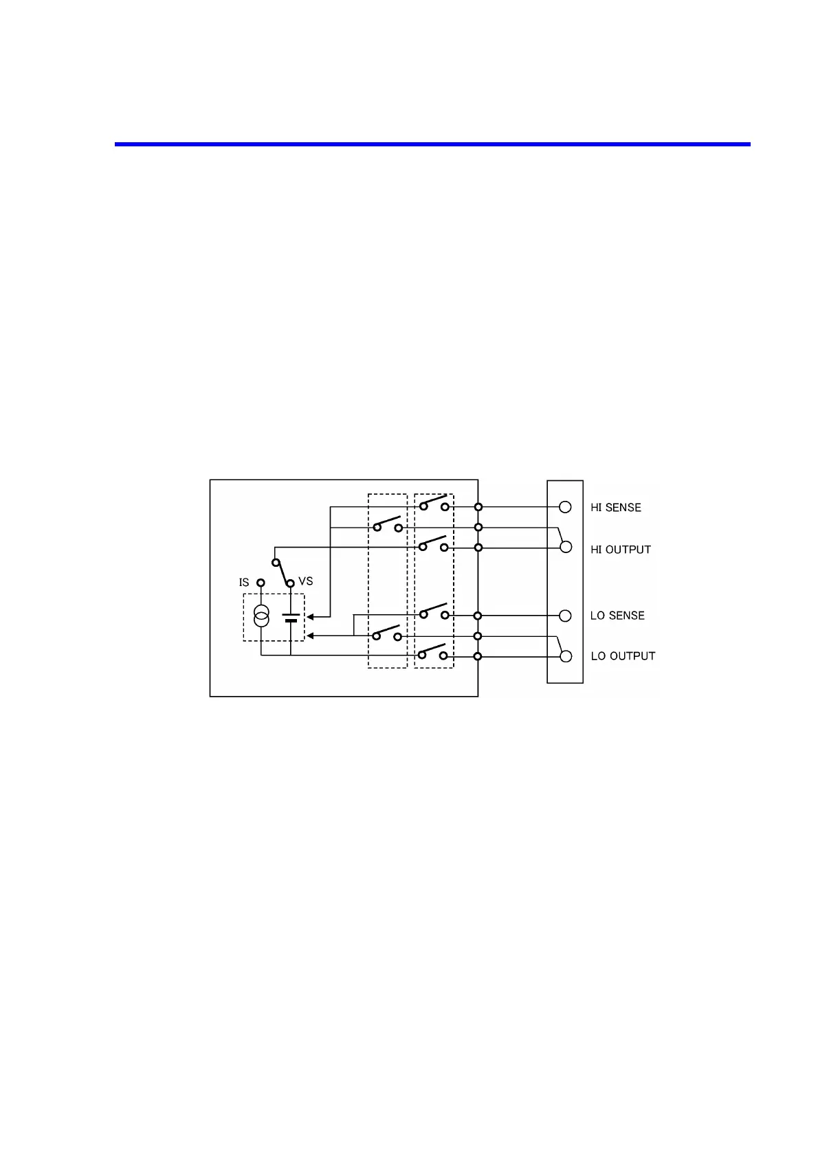
Figure 4-1 below shows the internal wire connection of the 6146/6156.
The output terminals are cut off from the internal circuits by the Operate and Standby relays in Standby
status.
Figure 4-1 Internal Wire Connection
4.1.2 Remote Sensing (2-Wire or 4-Wire Connection)
When connecting the 6146/6156 and the load, connect with 2-wire or 4-wire connection, while considering
the following conditions:
• Apply 2-wire connection if the output current is relatively low and the lead resistance does not mat-
ter.
• Apply 4-wire connection if the output current is relatively large and the lead resistance matters.
• 2-wire connection is applied even if setting to 4-wire connection in case of 30 mV range, 300 mV
range or current source (IS). The SENSE terminals are unavailable.
2-wire connection and 4-wire connection are switched by MENU operation.
2-wire connection: 2w is displayed.
4-wire connection: 4w is displayed.
A voltage sensing current of 80 μA flows when the voltage is set to the full scale.
2-Wire/4-Wire OPR/STBY
 Loading...