6146/6156 DC Voltage/Current Generators Operation Manual
5.5.3 Interface Signals
5-15
5.5.3 Interface Signals
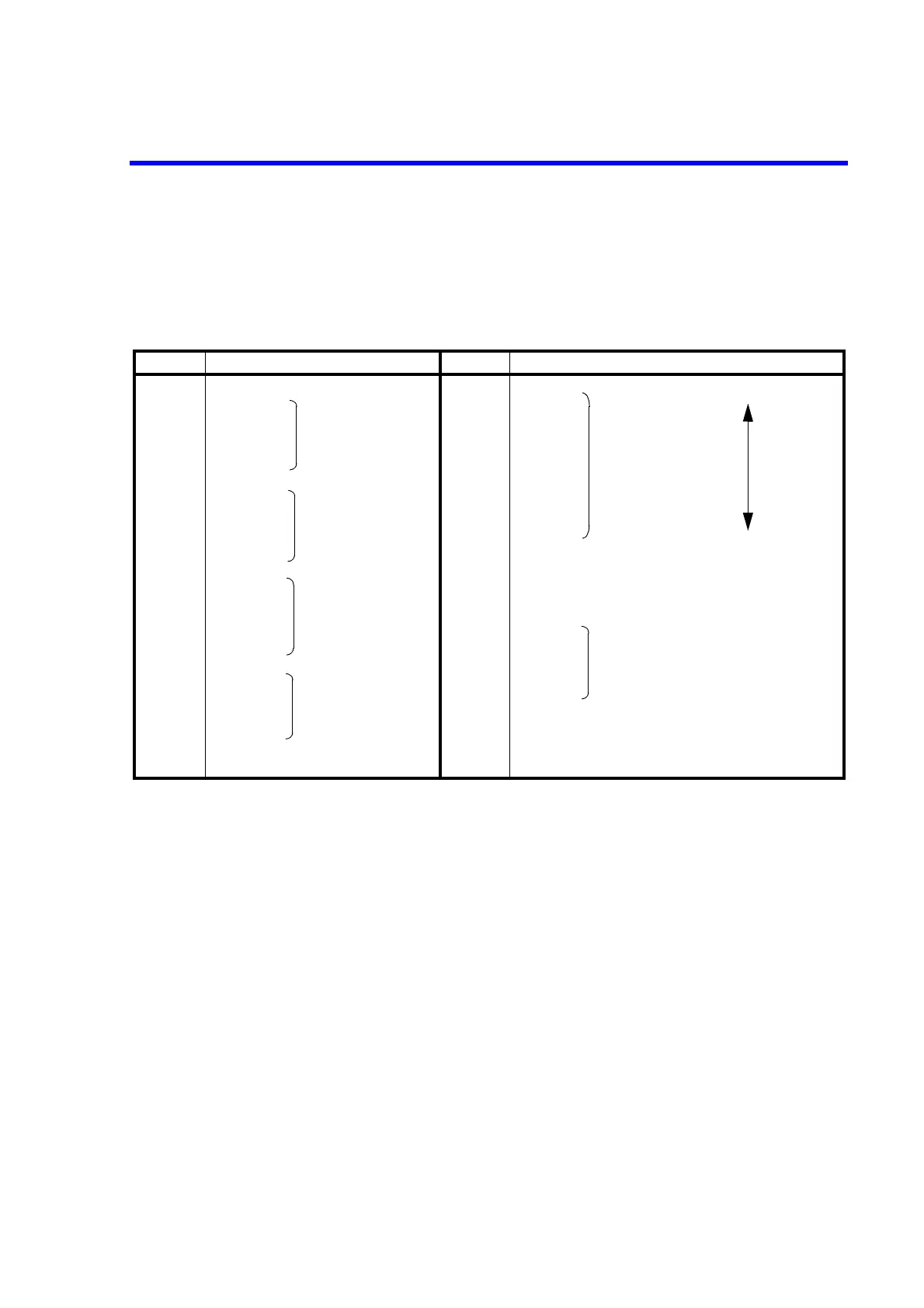
The following shows the pin arrangement and code list.
Table 5-3 BCD Parallel Connector Pin Arrangement and Code List
Pin number Signal name Pin number Signal name
1 0V (GND) 19 30 V High
Low
2 1 20 3 V *2
32
10
1
digits
21 300 mV Range code
44
(10
0
digits) *1
22 30 mV Priority
5 8 23 200 mA
6 1 24 30 mA
72
10
2
digits
25 3 mA
84
(10
1
digits) *1
26 30 V *3
98 27Polarity
10 1 28 2
10
5
digits (10
4
digits) *1
11 2
10
3
digits
29 Output ON
12 4
(10
2
digits) *1
30 1
13 8 31 2
10
0
digits (NC) *1
14 1 32 4
15 2
10
4
digits
33 8
16 4
(10
3
digits) *1
34 NC *4
17 8 35 NC
18 1
10
5
digits (10
4
digits) *1
36 LOAD
Used connector: 57LE-40360 (Amphenol) or equivalent
*1: Output level setting for the 6146
*2: When more than one range code are logic "1," there is a priority.
*3: The 30 V range is judged by a logical disjunction (OR). (The 30 V range assigned to pin number 19 corre-
sponds to the 10 V range of the former model.)
*4: NC (Non-Internal Connection): Do not use as a junction terminal.
 Loading...