ADPRO iFT Series Hardware Installation Manual
27817_08 35
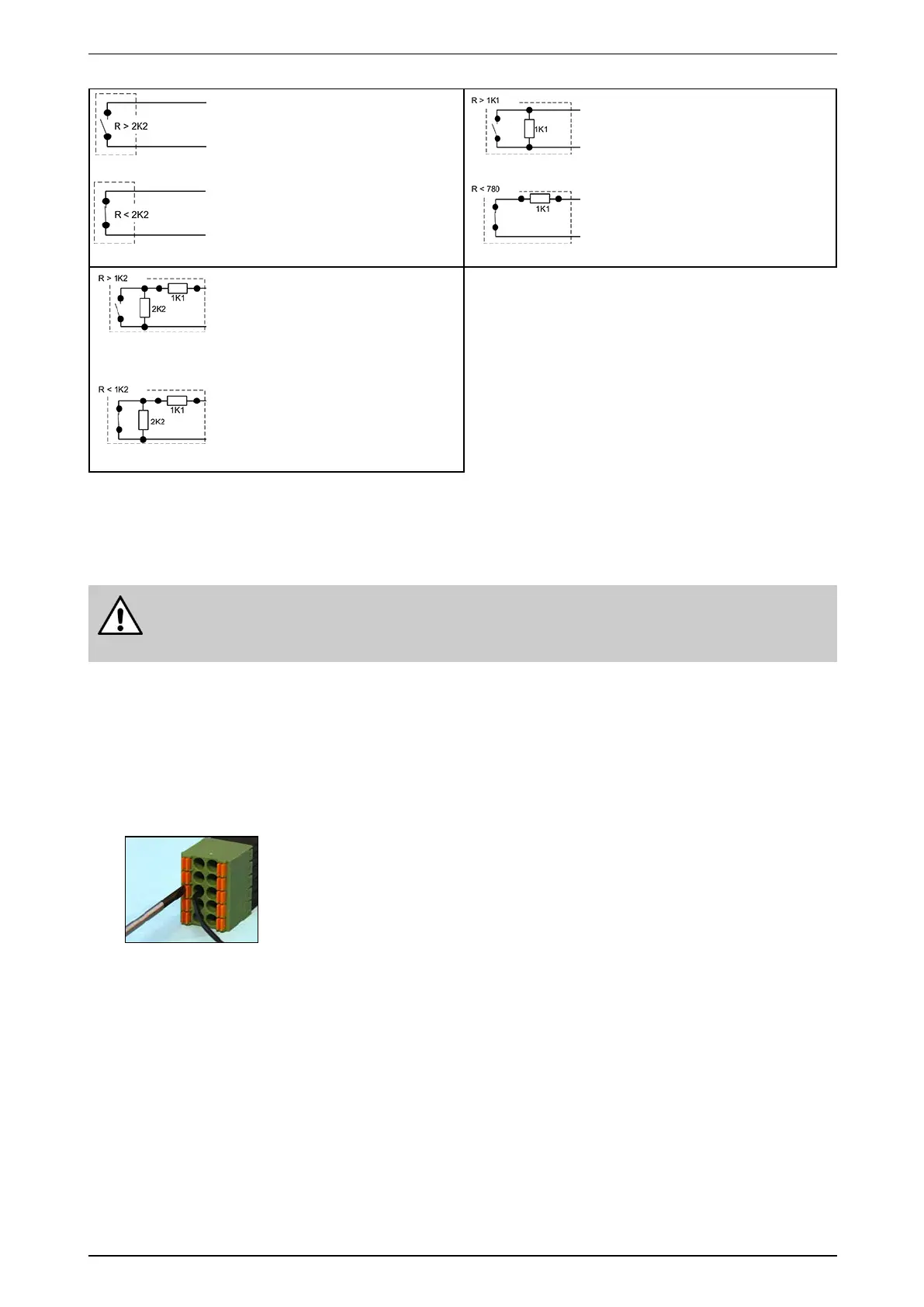
Normallyopen–NEOL
Shortcircuit=alarm
Opencircuit=idle
(Defaultsetting)
Normallyopen–SEOL
Shortcircuit=alarm
1K1=idle
Opencircuit=tamper
Normallyclosed–NEOL
Shortcircuit=idle
Opencircuit=alarm
Normallyclosed–SEOL
Shortcircuit=tamper
1K1=idle
Opencircuit=alarm
Normallyopen–DEOL
Shortcircuit=tamper
1K1=alarm
3K3=idle
Opencircuit=tamper
Normallyclosed–DEOL
Shortcircuit=tamper
1K1=idle
3K3=alarm
Opencircuit=tamper
7.2.3 Connecting Inputs and Outputs
Dependingonthetype,theI/OcardcanbeequippedwithDinkle(standard)orPhoenixspringinsertion
connectors.Forbothtypesyouneeda2mmslottedscrewdriver.
Warning!
Althoughthepicturebelowshowsonlytheconnector,itisstronglyrecommendedtoconnectthe
wireswiththeconnectorspluggedintothecard.Wiringahandheldconnectormaycauseinjuries.
WiringtoDinkleandPhoenixconnectorsisidentical,exceptthatthepositionoftabsandholesisswapped.The
pictureintheprocedurebelowshowsaPhoenixconnector.
Toconnectinputsandoutputs,proceedasfollows:
1. Pushtheslottedtabfirmlyinwardswiththescrewdriver.
2. Insertthestrippedwire(6–7mm)intothecorrespondingroundholeasdeeplyaspossible.
3. Releasethetabandpullthewiretocheckifitisproperlyfitted.
Wiregauge:
Solidandstranded:16–24AWG
(diam.1.3–0.5mm)