iFT Series Hardware Installation Manual ADPRO
54 27817_08
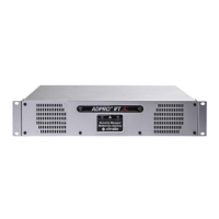
OntheinternalMIOcard,settheRS-485jumpertothe2-wireposition(A).
MIO card Next Generation
A RS-485PTZjumper:2-wiresetting
(defaultsetting–seeNotebelow)
B RS-485PTZjumper:4-wiresetting
Note
OnsystemsproducedfromtheendofApril2015,thedefaultsettingoftheRS-485PTZjumperis
2-wire.Onoldersystems,the4-wiresettingwasdefault.Ifyouexperienceanyproblemswhen
connectingdevicestotheMIOcard,checktheRS-485PTZjumpersetting.Changeitifnecessary.
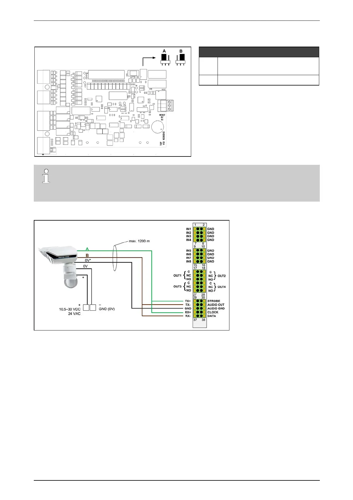
Connectthewiresasshownbelow:
(*)SomePIRmodelshaveseparate0Vterminalsfordataandpower;onothermodelsthereisonlyonecommon0V
terminal.
Makesuretobridgethefollowingconnections:
l TX+withRX+
l TX–withRX–
ThePIRdetectorsarepoweredlocallybyapoweradapter.
YoucanplacelocallypoweredPIRdetectorsatthemaximumdistanceof1200mforRS-485cables.Makesure
thatthereisnodifferenceinearthpotentialbetweentheXOdeviceandthePIRdetector.