Home
Agilent Technologies
Laboratory Equipment
5100
Agilent Technologies 5100 Service Manual
4
of 1
of 1 rating
312 pages
Give review
Manual
Specs
To Next Page
To Next Page
To Previous Page
To Previous Page
Loading...
Agilent 5110/5100
IC
P-OES Service Manual
Agilent Restrict
ed
113
4
Removal/ Installation, Replacement and Adjustment
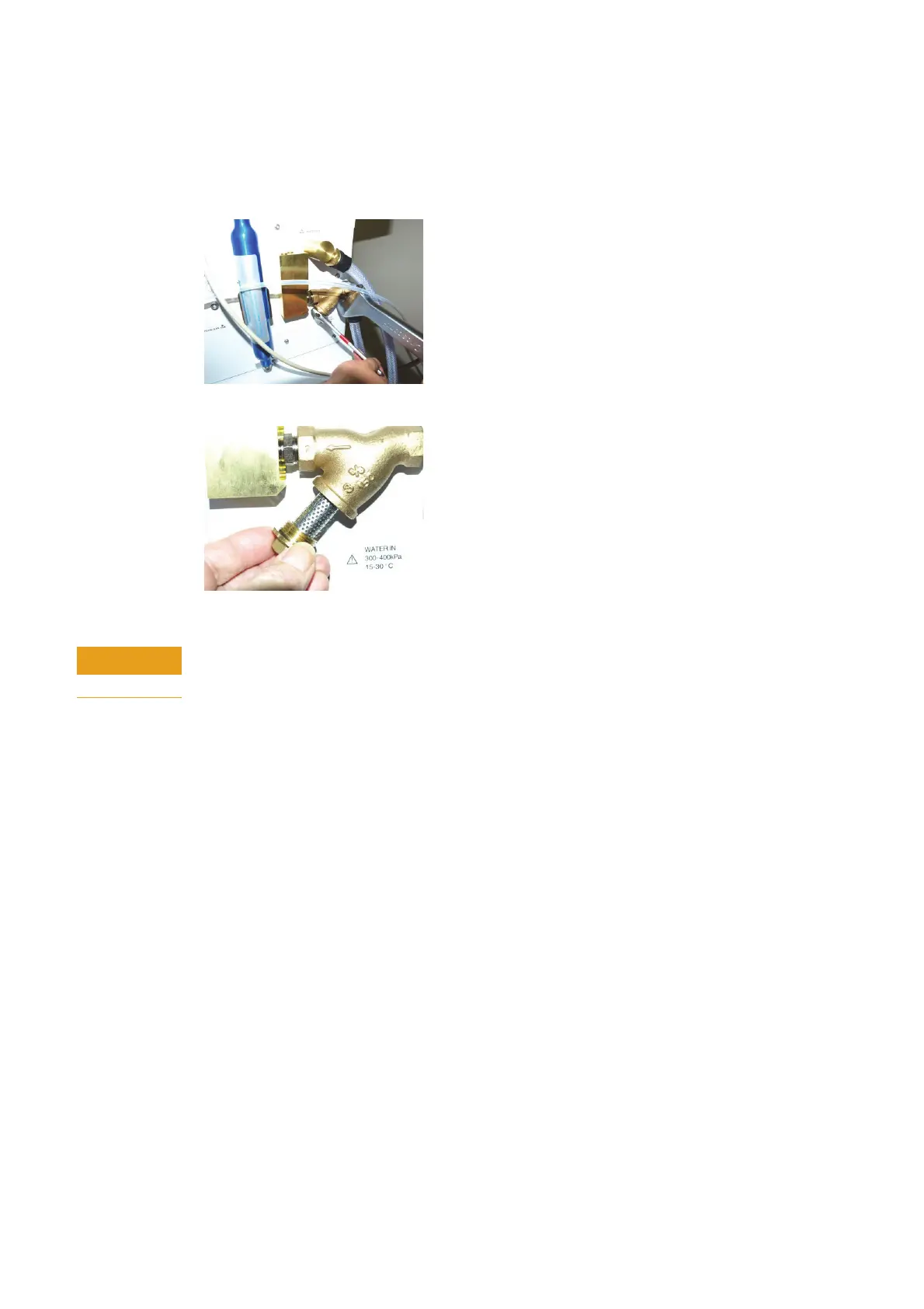
Water filter
Water filter
1
To access water filter remove nu
t with 17mm ope
n ended wrench.
2
Remove filter and clean as required.
CAUTION
Before securing water module in
to chassis switch on water c
ooling and ensure there are no
water leaks.
112
114
Table of Contents
Table of Contents
3
Safety Information Precautions
12
General
13
Handling of Gas
15
Call Qualification Customer Help Guide
18
Functional Issues
18
Performance Issues
20
Spare Parts
20
General Information Specifications
24
Environmental Conditions and Utility Requirements
24
General Information
24
Agilent 5110/5100 ICP-OES System Description
26
System Overview
26
Instrument Layout
28
Instrument Configurations
30
Power Distribution
31
Instrument Control
33
Power On/Off Switch Indicator
35
Mains Power Module (MPM) Self Check
36
Initial
36
Stable
36
Off
36
Instrument Relay
36
RF Power Supply Relay
37
Heater
37
Blower
37
Shutdown
38
Instrument Status Indicator
39
Advanced Valve System (AVS) Indicator
40
Plasma RF
41
RF Interlocks
43
Sample Introduction
44
Description
44
Nebulizers
45
Glass Concentric Nebulizer
46
Seaspray Nebulizer
46
Ultrasonic
46
Spraychambers
47
Double-Pass Glass Cyclonic (Twister)
47
Optics
49
Description
49
Pre Optics Assembly
51
Polychromator Assembly
52
Shutter
53
Pilot Mirror
53
Entrance Slit
53
Collimating Mirror
53
Prism
53
Grating
53
Camera Mirror
54
Full Illumination LED Fiber Optic Source
54
Camera Assembly
54
CCD Layout
55
Gas Control
56
Water Control
58
Air Cooling
60
Removal/ Installation, Replacement and Adjustment
61
Tools and Supplies for 5110 Instrument
62
Removal Hierarchy
65
Instrument Covers
67
Left Hand Side Cover
67
Left Hand Top Cover
68
Chimney
69
Right Hand Side Cover
70
Top Right Hand Cover
71
Front Left Lower Cover
73
Torch Compartment Door
73
Sample Introduction
74
Torch
74
Torch Loader Micro Switch
75
Torch Loader
77
Axial Cone Cooling Interface
80
Peristaltic Pump
81
Advanced Valve System (AVS)
82
Switching Valve Head
83
Changing Valve Head Type
84
Instrument Electronics
85
Instrument Control Module
86
Mains Power Module
87
Standby Power Switch
87
Mains Filter
88
Circuit Breaker and Power Socket
88
RF System
89
RF Oscillator
89
RF Current Sensor
95
Igniter
96
SSRF Filter Board
97
SSRF Control Board
98
RF Power Supply (RFPS)
98
SSRF PSU Interface Board
99
RFPS Cradle
99
Air Cooling
101
Air Cooling Filter
101
Cooling Fan
101
Air Cooling Flow Sensor
102
Plasma Interlocks and Sensors
103
RF Door Interlock Switches
103
Plasma Sensor
104
RF1 (SSRF Exhaust) Temperature Sensor
105
RF2 (Plasma Exhaust) Temperature Sensor
105
Gas System
106
Gas Control Module
106
Gas Option
108
Gas Filter
109
Water System
111
Water Control Module
111
SSRF Water Inlet Temperature Sensor
112
Water Filter
113
Optics System
114
Pre Optics System
114
Axial Window
115
Radial Window
116
Mirror Axial M1
117
Mirror Axial M2
118
Mirror Axial M3
119
Mirror Radial M1
120
Viewing Height Motor
120
Mirror Radial M2
121
Beam Combiner and PCA Board
122
Thermal Stabilizer
123
Polychromator
126
Polychromator Access
127
Collimator and Focus Mirror Access
129
Pilot Mirror M5
129
Entrance Slit
130
Grating Prism Assembly
132
Camera Access and Removal
132
Optical Alignment
137
• Pre-Optics Alignment
137
Polychromator and Camera Alignment
139
Camera Image Location Adjustments
140
Focus Adjustments
142
Argon Ratio Adjustment
149
Troubleshooting Low Analytical Sensitivity
156
Perform an Instrument Test
156
Sensitivity Failure - Analysis Table
157
Low Sensitivity Fault Finding Diagnostics
158
Blocked Nebulizer
160
Blocked Injector Tube
161
Pump Tubing
161
Organic Samples
161
Incorrectly Prepared Standards
161
Conditions Not Optimized
161
Camera Condensation
161
Failing Precision (Relative Standard Deviation)
164
Identifying the Problem
164
Precision Failure Analysis Table
165
Precision - Fault Finding Diagnostics
165
V-Groove Nebulizer
167
Concentric Glass Nebulizer
167
Torch
167
Contamination in Spraychamber
167
Pump/Pump Tubing
168
Instrument Calibration
168
Running Aqueous Analysis after Non-Aqueous Analysis
168
Partially Soluble Salts
168
High Salt Content
169
Customer Diagnostics and Problem Solving
171
Testing Nebulizer Back Pressure
172
Selecting Diagnostic Gauge Suites
174
Custom Gauges
175
Gas Supply Gauges
175
Plasma Gas Flow
175
Auxiliary Gas Flow
175
O2 Injection Gas Flow
175
Option Inlet Pressure
175
Water Cooling Gauges
176
RF Water Flow
176
Camera Water Flow
176
Water Inlet (°C)
176
Instrument (°C)
176
Optics Gauges
177
Polychromator (°C)
177
Polychromator Purge
177
Peltier (°C) Camera
177
Thermal Stabilizer (°C)
177
Camera Water Flow
177
Plasma Gauges
178
RF Water Flow
178
RF Power (Kw)
178
Plasma Exhaust (°C)
178
Plasma Gas Flow
178
Auxiliary Gas Flow
178
General Gauges
178
Instrument (°C)
178
Mains Frequency
178
Mains Voltage
179
Atmospheric Pressure
179
Camera Water Flow
179
Other Gauges
179
Argon Inlet Pressure
179
Plotting Gauge Data on a Graph
179
Testing RF Water Flow
181
Purge Gas Flows Test
181
Selecting Instrument Tests
183
Instrument Tests: Functions and Failure Modes
185
Subsystem Communication Test
185
Air Flow Test
185
Water Flow Test
185
Gas Flows Test
186
RF Generator Test
186
Camera Test
186
Optics Test
187
Instrument Performance Test
187
Advanced Valve System Test
187
Reports
188
Service Diagnostics and Fault Finding
189
Internet Protocol (IP) Address Configuration
190
Configure Controlling Computer IP Address
190
Configure Instrument IP Address
191
Discover a Lost IP Address
193
Status Diagnostic Codes
194
Software Error Messages
195
Instrument Startup Constraints
196
Engineer Service Diagnostic Screens
197
ICP Expert Diagnostics
197
Typical Event Logs (Plasma)
205
Plasma Start up Typical Event Log
205
Plasma Extinguished Typical Event Log
205
Poly Align Diagnostics
206
Developing a Manganese (Mn) Method
208
Flow Chart Diagnostics
210
Failure Analysis
210
Failure Analysis of Instrument
211
Failure Analysis of Software (SW1)
213
Failure Analysis of Plasma (PL1)
214
Failure Analysis of RF (RF1)
215
Failure Analysis of Torch Loader (TL1)
216
Failure Analysis of Torch Compartment (TD1)
217
Failure Analysis of Gas Control System (GC1)
218
Failure Analysis of Peristaltic Pump (PC1)
219
Failure Analysis of Water Control System (WC1)
220
Failure Analysis of Pre Optics System (PT1)
221
Failure Analysis of Optics System (OP1)
222
Failure Analysis of Camera System (CS1)
223
Failure Analysis of Wavelength Calibration Routine (WA1)
224
Failure Analysis of Thermal Stabilizer (TS1)
225
Failure Analysis of SSRF Water Cooling (SWC1)
226
Inter-Wiring Diagrams
227
Support Parts
233
Instrument Covers
234
Instrument Control Module
236
Mains Module - Power Supplies
237
Axial/ Radial Pre Optics Assembly
238
Left Side RF Box/ Pre Optics
240
Plasma Compartment
242
RF Box Lower
243
Gas Control
244
Polychromator
246
Water Module
247
Peristaltic Pump
248
Wiring Harness/ Looms
249
Air Cooling
253
Advanced Valve System (AVS)
254
Parts Index
255
Itroubleshoot/Parts Predict Problem Solving Table
258
Installation Guide (5110 ICP-OES) Introduction
266
Introduction
266
Standard Installation Times
267
Install ICP-OES System
268
Hardware Installation
268
Mains Connection
270
Gas Connection
270
Water Chiller Connection
271
Water Chiller Connection to the Spectrometer
272
Software Installation
273
PC Hardware Requirements
274
Installing the ICP Expert Software
274
Software Registration
274
Polychromator Software (Polyalign.exe)
276
Printer Configuration
276
ICP Expert Help System
276
Sample Introduction Setup
277
Confirm System Performance for 5110/5100
278
Start a Plasma
278
From Shutdown Mode (or for the First Time)
278
Instrument Calibration
281
Wavelength Calibration and Detector Calibration
281
Instrument Performance Tests
283
Sample Introduction
283
Sample/Standard Solution
283
Blank
284
Rinse
284
Performance Tests
284
Instrument Conditions
284
Performance Test Procedure
285
Initial Performance Test
292
Inspect and Clean the System
293
Accessories
294
Status Results Table
296
Performance Tests
297
Preventative Maintenance Requirements
298
System Description and Specifications
300
Cooling Requirements
300
Water Cooling System Location
301
Anti-Algae Requirements
301
Installation Hints
302
Assembling and Commissioning
302
Connection to the Spectrometer
303
Pre-Conditioning the Water Cooling System
303
Leak Testing
304
Routine Maintenance
304
Other manuals for Agilent Technologies 5100
User Guide
66 pages
4
Based on 1 rating
Ask a question
Give review
Questions and Answers:
Need help?
Do you have a question about the Agilent Technologies 5100 and is the answer not in the manual?
Ask a question
Agilent Technologies 5100 Specifications
General
Brand
Agilent Technologies
Model
5100
Category
Laboratory Equipment
Language
English
Related product manuals
5100 ICP-OES
66 pages
5110 ICP-OES
66 pages
Agilent Technologies 5975
192 pages
Agilent Technologies 5800
66 pages
Agilent Technologies 5890
16 pages
Agilent Technologies 5517B
102 pages
Agilent Technologies 5975 MSD
128 pages
Agilent Technologies 5975 Series
164 pages
Agilent Technologies 6460
28 pages
Agilent Technologies 7500 ICP-MS
659 pages
Agilent Technologies 7010 Series
242 pages
Nano Indenter G200
478 pages