Agilent 5110/5100 ICP-OES Service Manual Agilent Restricted 149
4 Removal/ Installation, Replacement and Adjustment
Argon ratio adjustment
You may find it easier to monitor the two ratios in the summary window (highlighted) when
adjusting rotation screws rather than comparing the 2 moving peaks. When aligned both lines
will overlap exactly.
Always refer back to constellation view (red cross hairs) for verification that peaks are within the
correct area otherwise they will show as very noisy when trying to adjust.
In the above example the peaks are flaring slightly. To reduce this, adjust the Integrate time
down.
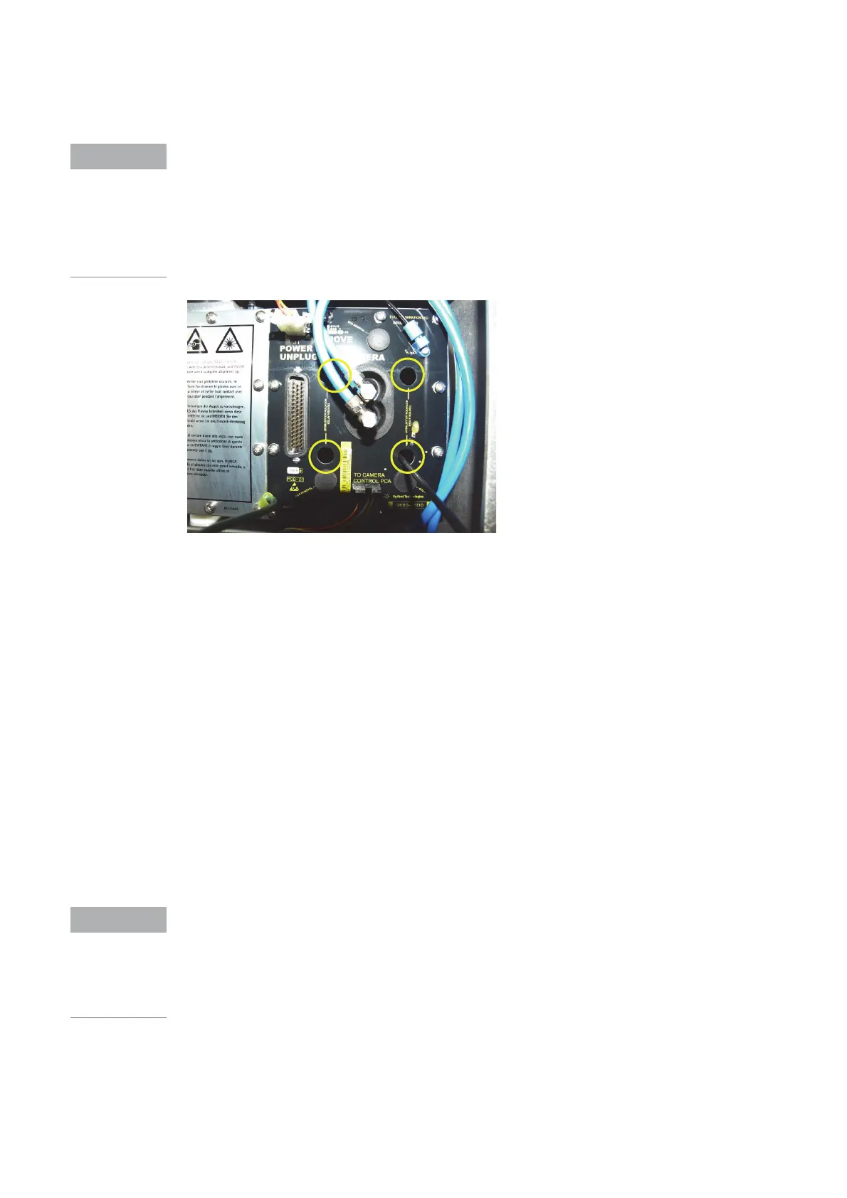
15 Gently tighten the four hex head screws that retain the camera and verify that no further
rotation adjustments are required.
16 Tighten the screws completely and verify alignment.
17 Replace the rubber plugs in the camera access plate.
18 Replace all polychromator outer box covers.
19 Verify location and focus adjustments are correct. Adjust as necessary.
20 Proceed to the instrument argon ratio adjustment.
Argon ratio adjustment
The software tool used to align the polychromator argon ratio is the registration page. The
argon ratio adjustment positions the focus mirror at the correct position for the wavelengths of
the image to overlay the camera DLA locations. By moving the focus mirror across the camera
DLAs to the position where the best peak response for all elements is achieved. The DLA
adjustment screw is the only adjustment made to during the argon ratio adjustment.
Polychromator and camera alignment will change as the polychromator temperature stabilizes.
Adjustment to the polychromator and camera assemblies should only be done when the
polychromator temperature is 35°C as reported by the instrument software.
Access to the focus mirror adjustment screws does not require removal of any polychromator
outer box covers. To access the focus mirror adjustment screws, remove the polychromator
access cover at the left side of the instrument.
 Loading...


