148 Agilent Restricted Agilent 5110/5100 ICP-OES Service Manual
4 Removal/ Installation, Replacement and Adjustment
Optical alignment
11 Using the DLA mirror adjustment screw adjust the Ar 706.722nm peak to a ratio of 1.00 (+/-
0.1) (DLA screw adjusts constellation vertically).
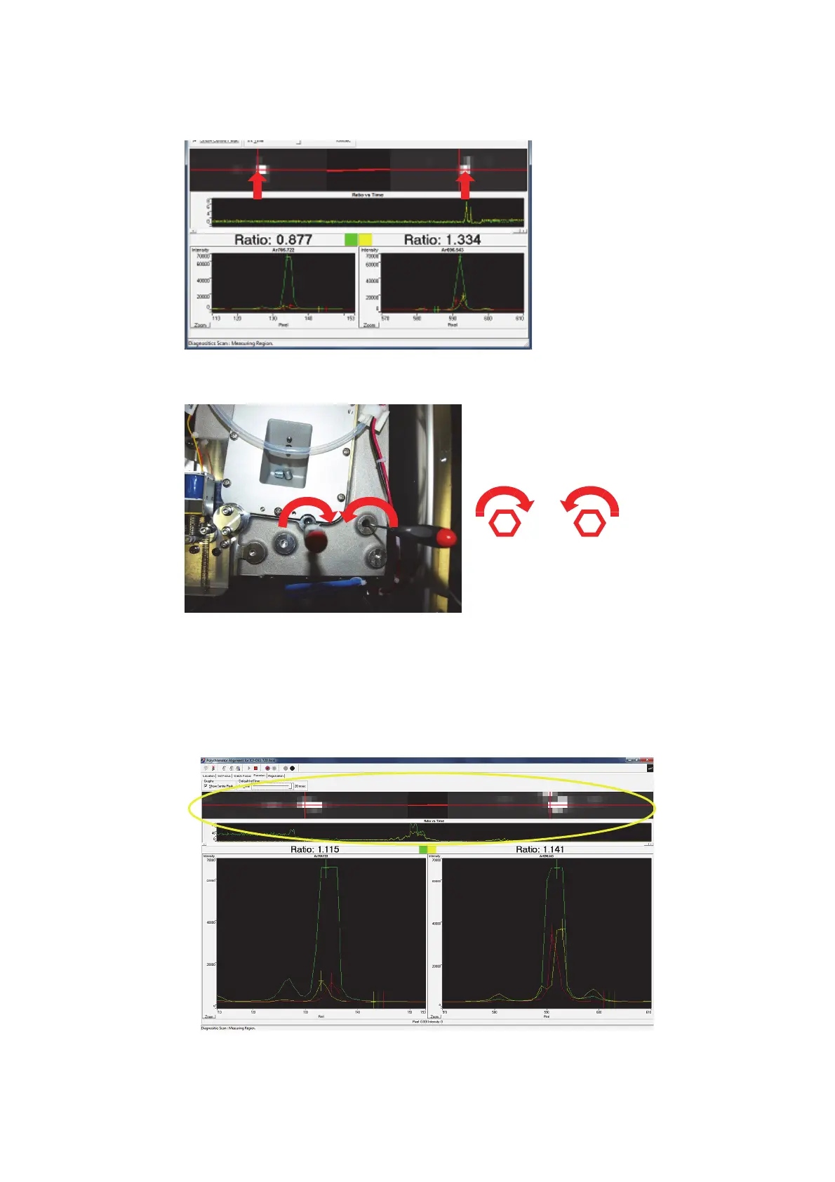
12 Using two 2mm hex wrenches, adjust the camera rotation screws until both ratio figures are
equal to 1(+/- 0.1).ie: the constellation peaks are aligned on the horizontal red line. Rotate
Left screw Clockwise to increase Ar 706 line. The right hand screw needs to be adjusted in
the opposite direction to the left hand screw to allow rotation and maintain constant tension
on the Camera housing.
13 Re-position the Ar 706.722nm peak with the DLA and wavelength focus mirror adjustment
screws to return 706.722 ratio back to ~1.0 after rotation adjustment.
14 Repeat steps 11 to 13 until both displayed ratios are equal and the red horizontal bar in
between the intensity maps is horizontal.
Adjusting screws looking down
on the Poly Casting
 Loading...


