Agilent 5110/5100 ICP-OES Service Manual Agilent Restricted 147
4 Removal/ Installation, Replacement and Adjustment
Optical alignment
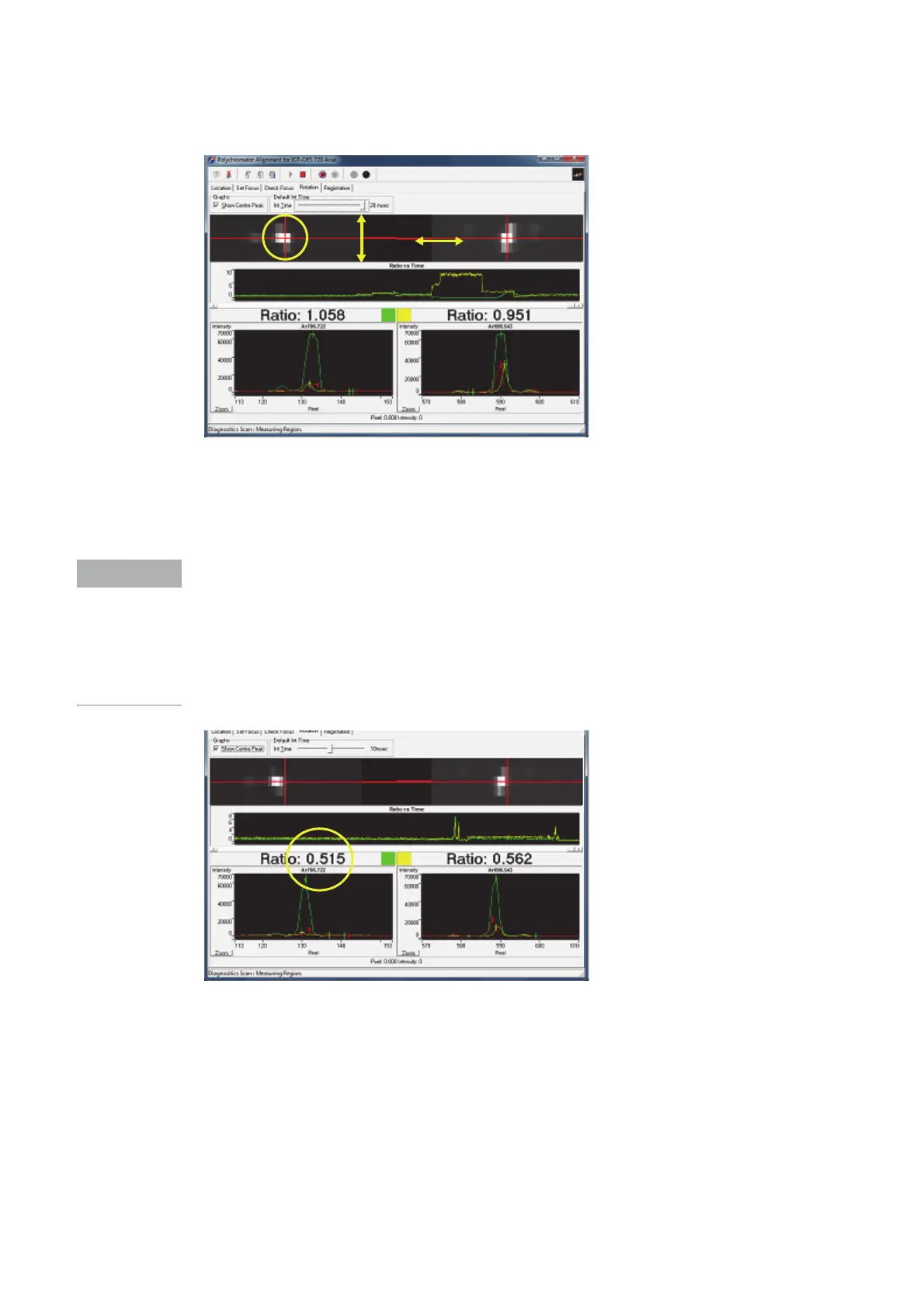
9 Using the DLA mirror adjustment screw and the intensity map, position the Ar 706.722nm
peak vertically onto the horizontal red line.
10 Using the wavelength mirror adjustment screw and intensity map, position the Ar 706.722nm
peak horizontally onto the cross hair).
In the above screen shot example the Ratio 1.058 (on the left) represents the ratio of the
brightness of 2 pixels next to each other (white pixel to the pixel next to it in the yellow circle).
If the pixels being reviewed are too bright (flaring) reduce the integrate time to lower the
intensity. (Refer example in step 14)
When using Poly Align the viewing mode (Axial or Radial) will default to the mode that was
previously being used with ICP Expert. To Change viewing mode, go back to ICP Expert and
select the appropriate mode then return to Poly align.
 Loading...


