Valve Control
Valve control examples
198
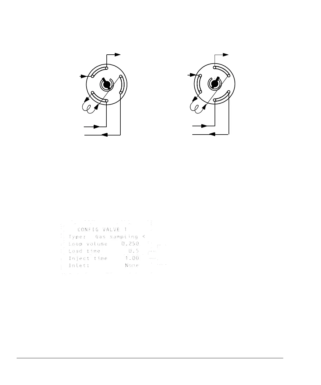
Figure 33 A gas sampling valve
Carrier gas may be provided by an (optional) auxiliary gas channel. To do this,
configure the column and specify an Aux # channel as the inlet. The Aux #
channel then becomes programmable with four operating modes.
The sampling valve cycle is:
1. The sampling valve rotates to the Load position. Load time begins. Valve
is not ready.
2. Load time ends. The valve becomes ready.
3. If everything else is ready, the GC becomes ready.
If everything else is not ready:
To column
To column
Inject
position
Sample in
Sample out
Sample in
Sample out
Carrier in
Load
position
Loop
Load position—the loop is flushed with a stream of the sample gas. The
column is flushed with carrier gas.
Inject position—the filled loop is inserted into the carrier gas stream. The
sample is flushed onto the column. The run starts automatically.
Time in minutes that the valve remains in
the load position before becoming ready
Time in minutes that the valve remains
in the inject position before returning to
the load position
Loop volume and Inlet: are
information only—they do not affect
operation.
 Loading...


