130 Chapter 4
Basic Digital Operation
Using Waveform Markers
Waveform Marker Concepts
The signal generator’s ARB formats provide four waveform markers to mark specific points on a waveform
segment. You can set each marker’s polarity and marker points (on a single sample point or over a range of
sample points). Each marker can also perform ALC hold or RF Blanking and ALC hold.
Marker File Generation
Generating a waveform segment (see page 107) automatically creates a marker file that places a marker
point on the first sample point of the segment for markers one and two.
Downloading a waveform file (as described in the E4428C/38C ESG Signal Generators Programming
Guide) that does not have a marker file associated with it causes the signal generator to automatically create
a marker file but does not place any marker points.
Marker Point Edit Requirements
Before you can modify a waveform segment’s marker points, the segment must reside in volatile memory
(WFM1). Refer to the section, “Loading Waveform Segments from Non-Volatile Memory” on page 113 for
more information.
In the dual ARB player, you can modify a waveform segment’s marker points either without playing the
waveform, or while playing the waveform in an ARB modulation format. In an ARB modulation format,
you must play the waveform before you can modify a segment’s marker points.
Saving Marker Polarity and Routing Settings
Marker polarity and routing settings remain until you reconfigure them, preset the signal generator, or cycle
the ESG power. To ensure that a waveform uses the correct settings when it is played, set the marker
polarities or routing (RF Blanking and ALC Hold), and save the information to the file header (page 92).
This is especially important when the segment plays as part of a sequence because the previously played
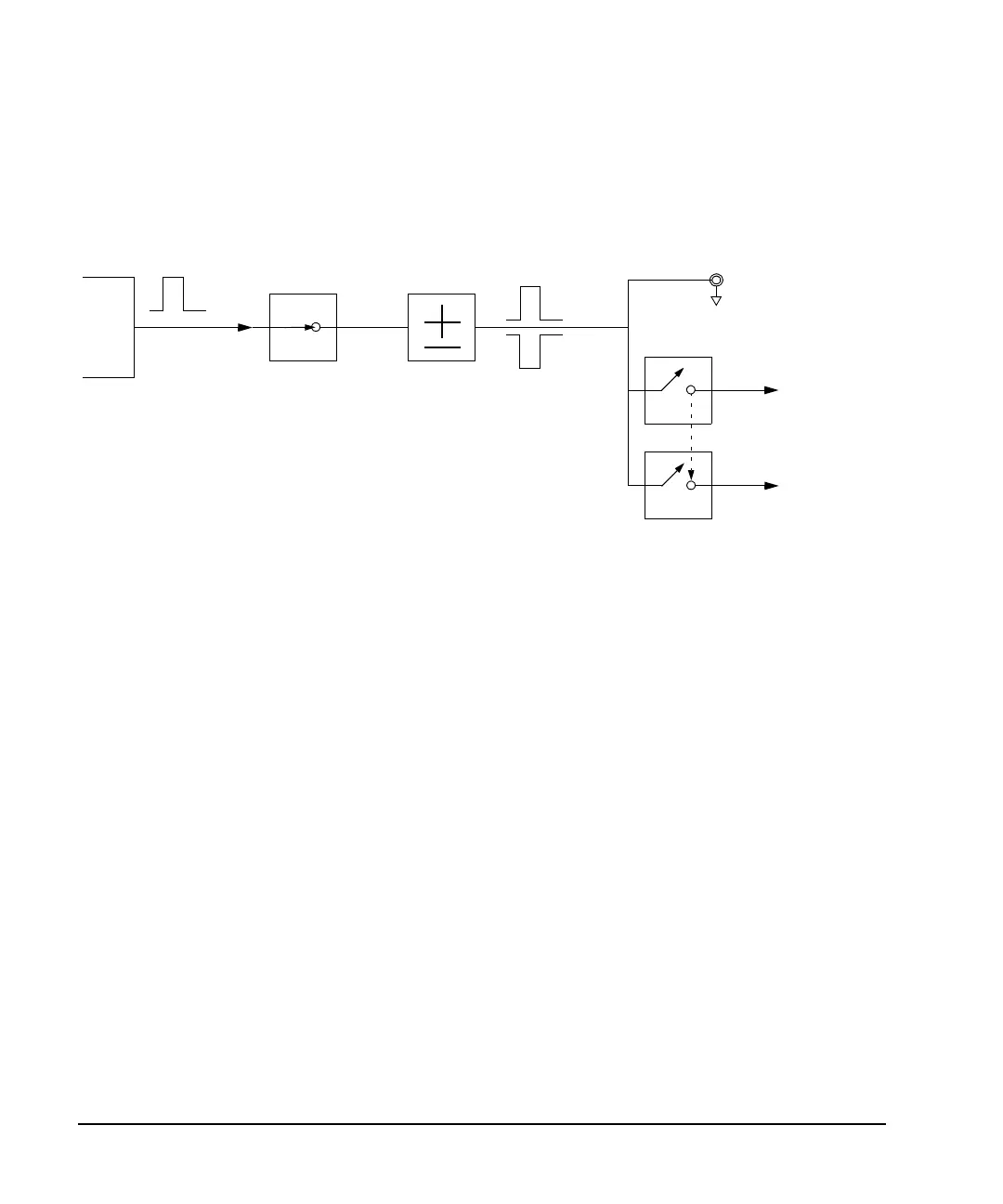
Marker
File
Bit
N
Marker
Polarity
Marker
N
RF Blank Off On
Marker
N
Blanks RF
when Marker
is Low
EVENT
N
Negative
Positive
Set Marker
On Off
Marker
N
ALC Hold Off On
Marker
N
Holds ALC
when Marker
is Low
When the signal generator encounters an enabled marker (described on
page 139), an auxiliary output signal is generated and routed to the rear
panel event connector that corresponds to the marker number (
N
).
The EVENT 3 and 4 connectors are pins on the AUXILIARY I/O connector
(connector locations are shown in Figure on page 41).
RF Blank Only: includes ALC Hold