230 Chapter 7
Digital Signal Interface Module
Connecting the Clock Source and the Device Under Test
Connecting the Clock Source and the Device Under Test
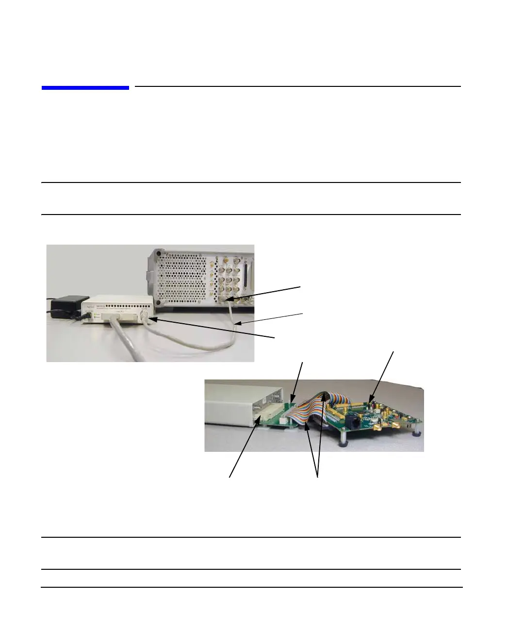
As shown in Figure 7-3 on page 222, there are numerous ways to provide a common frequency reference to
the system components (ESG, N5102A module, and the device under test). Figure 7-8 shows an example
setup where the signal generator supplies the common frequency reference and the N5102A module is
providing the clock to the device.
CAUTION The Device Interface connector on the interface module communicates using high speed
digital data. Use ESD precautions to eliminate potential damage when making connections.
Figure 7-8 Example Setup using the ESG 10 MHz Frequency Reference
NOTE You must disconnect the digital bus cable and the digital module while downloading
firmware to the ESG.
Signal generator 10 MHz Out
Freq Ref connector
Device interface connection
Device under test
Break-out board
User furnished ribbon cable(s) connect
between the device and break-out board.
Common Freq Ref cable
The clock to the device is in the ribbon
cable.