Chapter 18 647
Troubleshooting
Basic Signal Generator Operations
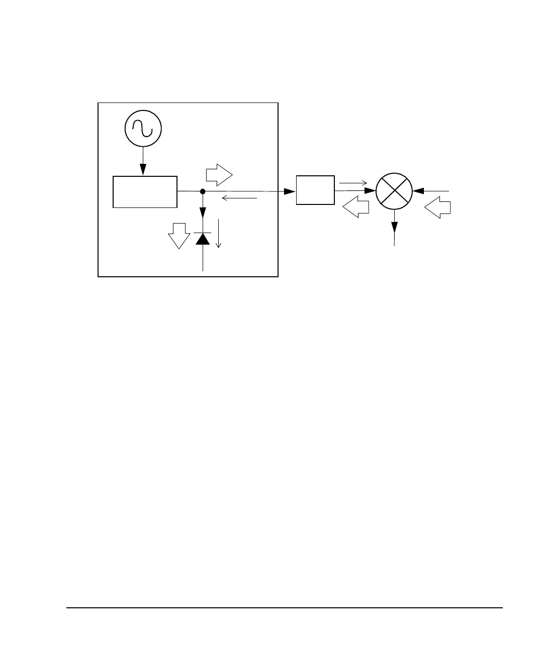
Figure 18-2 Reverse Power Solution
Compared to the original configuration, the ALC level is 10 dB higher while the attenuator reduces the LO
feedthrough (and the RF output of the signal generator) by 10 dB. Using the attenuated configuration, the
detector is exposed to a +2 dBm desired signal versus the −15 dBm undesired LO feedthrough. This 17 dB
difference between desired and undesired energy results in a maximum 0.1 dB shift in the signal generator’s
RF output level.
Signal Loss While Working with Spectrum Analyzers
The effects of reverse power can cause problems with the signal generator’s RF output when the signal
generator is used with a spectrum analyzer that does not have preselection capability.
Some spectrum analyzers have as much as +5 dBm LO feedthrough at their RF input port at some
frequencies. If the frequency difference between the LO feedthrough and the RF carrier is less than the ALC
bandwidth, the LO’s reverse power can cause amplitude modulation of the signal generator’s RF output. The
rate of the undesired AM equals the difference in frequency between the spectrum analyzer’s LO
feedthrough and the RF carrier of the signal generator.
Reverse power problems can be solved by using one of two unleveled operating modes: ALC off or power
search.
RF LEVEL
CONTROL
SIGNAL GENERATOR
OUTPUT CONTROL
MIXER
LO
IF
ALC LEVEL/
DETECTOR
MEASURES
+2 dBm
ALC LEVEL
DETECTOR
MEASURES
- 15 dBm
REVERSE
POWER
LO FEEDTHRU
= - 5 dBm
RF INPUT
= - 8 dBm
LO LEVEL
= +10 dBm
10 dB
ATTEN
RF OUTPUT
= +2 dBm