Chapter 16 553
W-CDMA Uplink Digital Modulation for Receiver Test
W-CDMA Uplink Concepts
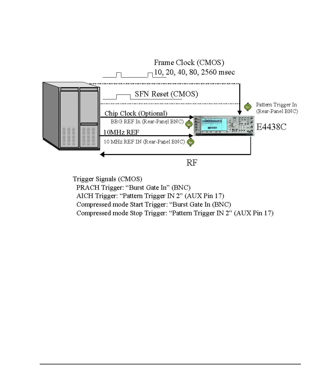
Figure 16-73 Cable Connections
System Triggering and Synchronization
Either the system frame number reset signal or the frame clock which is applied to the PATT TRIG IN
connector can be set as a system trigger signal. After a delay time defined by the sum of 1024 chips (T0 =
the standard timing offset between downlink and uplink), timing offset, and timeslot offset (plus 10 ms when
the SFN reset signal is used), a sync signal is generated to time align all other signals. The RF output signal
is generated after the fixed delay of the processing time by the hardware. This delay applies to DPCH mode
only. Refer to “Synchronization Diagrams” on page 562 for more information.
For increased measurement accuracy, the signal generator’s rear panel 10 MHz OUT frequency reference
can be utilized by other instruments in the test system.
Connector Assignments for W-CDMA Uplink
This section describes connector assignments for the W-CDMA uplink personality. The block diagram in
Figure 16-74 shows these connector assignments. Notice the front panel connectors are not used in the
uplink real-time signal generation personality.