Chapter 16 557
W-CDMA Uplink Digital Modulation for Receiver Test
W-CDMA Uplink Concepts
Signal Descriptions for W-CDMA Uplink
Figure 16-75 shows how W-CDMA uplink input and output signals align with respect to time. Notice that all
signals are aligned with the leading edge of the chip clock pulse.
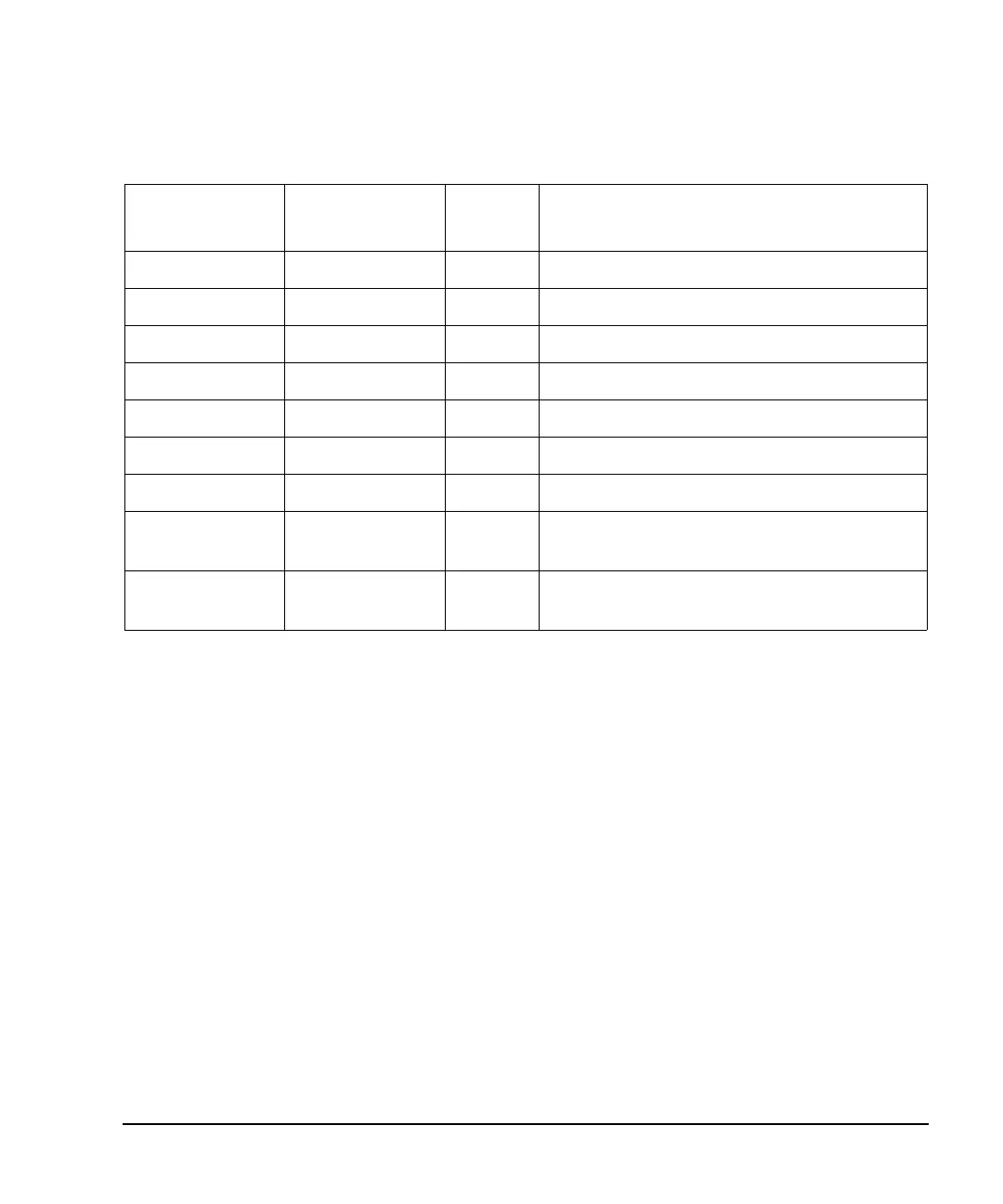
10 MHz IN BNC Input 10 MHz reference in.
10 MHz OUT BNC Output 10 MHz reference out.
EVENT 1 BNC Output Signal assigned by user. Default is none.
EVENT 2 BNC Output Signal assigned by user. Default is none.
EVENT 3 AUX I/O Pin 19 Output Signal assigned by user. Default is none.
EVENT 4 AUX I/O Pin 18 Output Signal assigned by user. Default is none.
DATA OUT AUX I/O Pin 7 Output Signal assigned by user. Default is none.
DATA CLOCK
OUT
AUX I/O Pin 6 Output Signal assigned by user. Default is none.
SYMBOL SYNC
OUT
AUX I/O Pin 5 Output Signal assigned by user. Default is none.
Table 16-6 Connector Descriptions for PRACH Mode (Continued)
Connector Label Connector Type Input/Ou
tput
Assigned Signal