556 Chapter 16
W-CDMA Uplink Digital Modulation for Receiver Test
W-CDMA Uplink Concepts
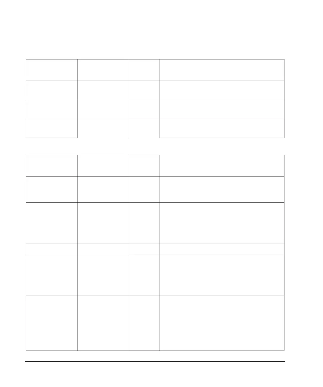
DATA OUT AUX I/O Pin 7 Output Signal assigned by user. Default is DPCCH raw
data.
DATA CLOCK
OUT
AUX I/O Pin 6 Output Signal assigned by user. Default is chip clock.
SYMBOL SYNC
OUT
AUX I/O Pin 5 Output Signal assigned by user. Default is sync trigger
reply.
Table 16-6 Connector Descriptions for PRACH Mode
Connector Label Connector Type Input/Ou
tput
Assigned Signal
PATTERN
TRIGGER IN
BNC Input Frame sync trigger. This signal determines the
SFN frame timing of the ESG so it is
synchronous with the base station.
PATTERN
TRIGGER IN 2
AUX I/O Pin 17 Input AICH trigger input. This connector pin is used
for the AICH trigger when operating in PRACH
mode. The AICH trigger instructs the signal
generator to generate the message part. The
Message Part data field must be set to AICH.
ALT POWER IN AUX I/O Pin 16 Input Unused.
BURST GATE IN BNC Input PRACH start trigger. The connector is used for
the PRACH start trigger when PRACH is
selected in the physical channel setup. The
PRACH start trigger instructs the signal
generator to begin the PRACH pattern.
BASEBAND
GEN REF IN
BNC Input External system clock in. This connector is used
for chip clock input when using external data
clock sources. To use an external signal source as
the data clock input, press
BBG Chip Clock Ext Int
to Ext or send the appropriate SCPI command.
This clock rate can be multiplied by setting the
Ext Clock Rate X1 X2 X4 softkey to either x2 or x4.
Table 16-5 Connector Descriptions for DPCH Mode (Continued)
Connector Label Connector Type Input/Ou
tput
Assigned Signal