468 Chapter 16
W-CDMA Uplink Digital Modulation for Receiver Test
Generating a Single PRACH Signal
adjusted. This resulted in the rate matching algorithm puncturing the data in order to fit it into a frame for the
given slot format.
Viewing the Modified PRACH Signal
This section uses the PSA settings from the procedure “Setting Up the E4440A PSA for the PRACH Signal”
on page 463.
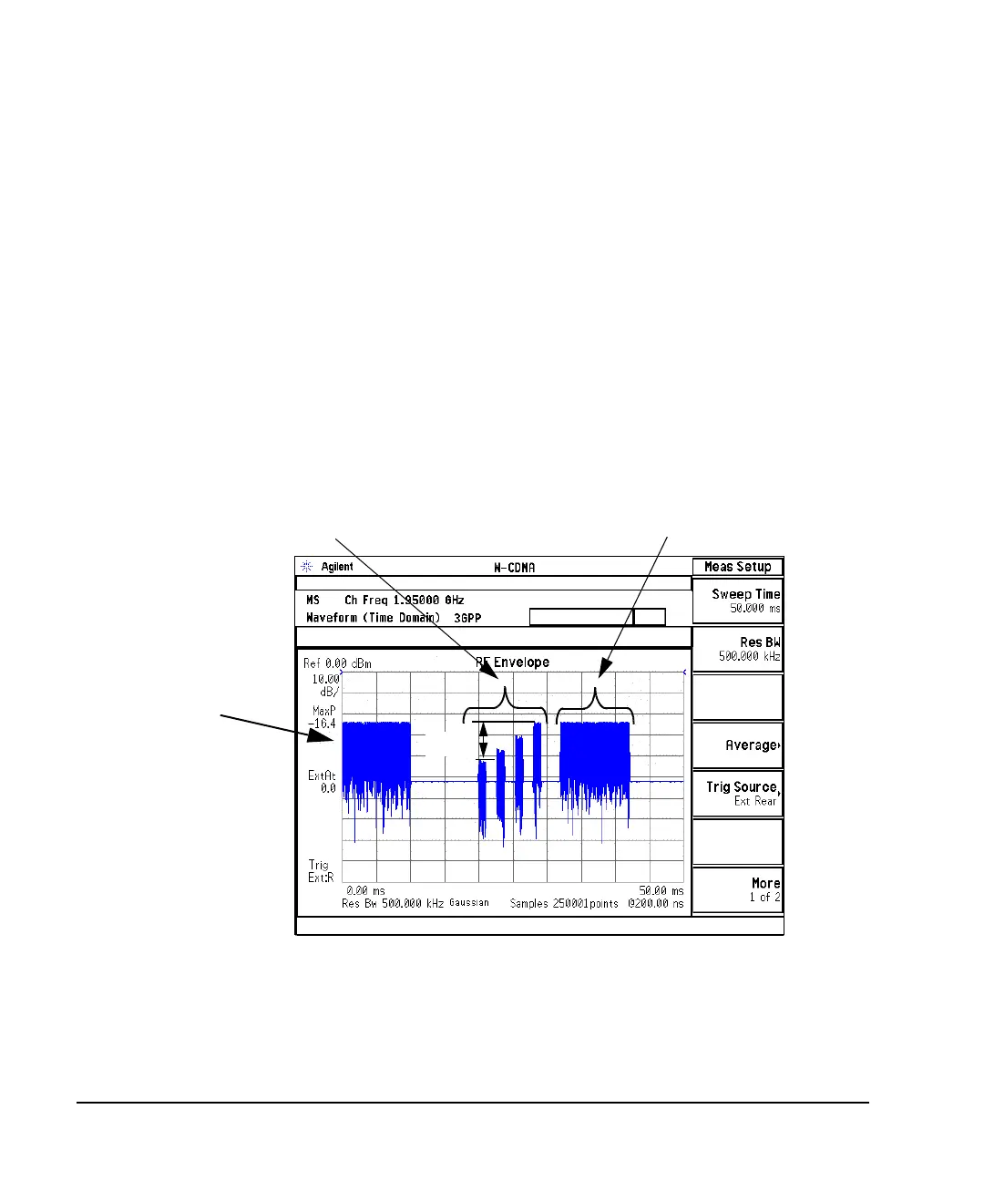
The PSA time domain measurement mode lets you view many of the PRACH parameters, since they are
time dependent. Figure 16-16 shows the PRACH signal after the modifications from the previous section
“Modifying the PRACH Physical and Transport Layers” on page 464 have been completed. Notice the PSA
sweep starts at the beginning of the message part and the message part has a time interval of 10 ms (there are
5 ms per vertical division). This is the result of setting the ESG PRACH trigger to message pulse and the
preamble TTI field to 10 ms. You can also see the preamble power ramping.
Figure 16-16 Displayed ESG Signal
Generating the AICH for the PRACH Message Transmission
The tasks in this procedure build upon the previous procedure, “Modifying the PRACH Physical and
Transport Layers” on page 464. This procedure uses a different PSA connection diagram
4 Preambles with Power Ramping 10 ms PRACH Message (TTI field)
PRACH Message
Trigger Starts the
PSA Sweep
21 dB