Chapter 16 559
W-CDMA Uplink Digital Modulation for Receiver Test
W-CDMA Uplink Concepts
Figure 16-76 DPCH Signal Alignment
Chip Clock Output Chip clock. 3.84 MHz is the default setting. RPS1
Trigger Sync Reply
(system sync output)
Output Response pulse of the frame sync trigger. The frame
sync trigger reply reports that the frame sync trigger
was received, and is used to adjust frame timing.
When the system trigger is not received, the system
sync output pulse is not generated.
RPS7
DPDCH Raw Data Output DPDCH data after 2nd interleaver (before spreading
and scrambling).
RPS2
DPCCH Raw Data Output DPCCH data after 2nd interleaver (before spreading
and scrambling).
RPS4
DPDCH Raw Data
Clock
Output The clock for DPDCH raw data. The rate depends on
the slot format (data rate) of DPDCH.
RPS3
DPCCH Raw Data
Clock
Output The clock for DPCCH raw data. The rate of this
clock is fixed at 15 kHz.
RPS5
10 ms Frame Pulse Output Indicates the frame boundaries for data generation. RPS6
TTI Frame Pulse Output Indicates the frame boundaries for TTI. RPS9
CFN #0 Frame Pulse Output Indicates the frame boundaries for CFN frame #0. RPS10
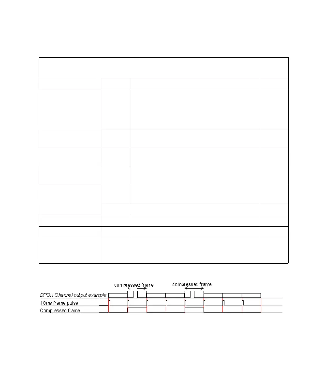
Compressed Frame Output This signal indicates the status of the compressed
frame. A 0 indicates a normal frame. A 1 indicates a
compressed frame.
RPS8
Table 16-7 Signal Descriptions for DPCH Mode (Continued)
Signal Label Input/
Output
Signal Description SCPI
Syntax