274 Chapter 5
Language Reference
[:SENSe]:BANDwidth Subsection
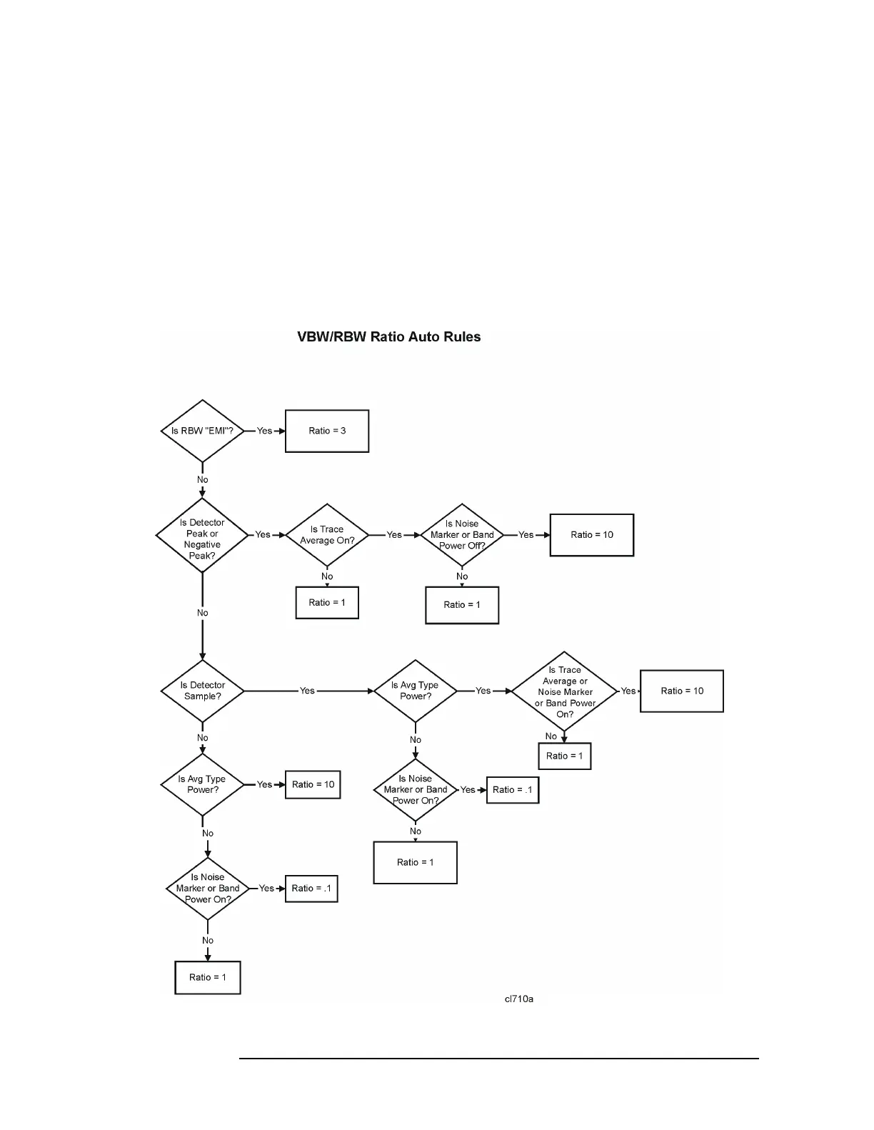
Refer to Figure 5-3, which is a flowchart that illustrates VBW and RBW Ratio
auto rules.
Factory Preset
and *RST: On
History: Added with firmware revision A.08.00.
Front Panel
Access:
BW/Avg, VBW/RBW, Auto Man
Figure 5-3 VBW and RBW Ratio Auto Rules
 Loading...


