Replaceable Parts
Major Assemblies
3-6
Major Assemblies
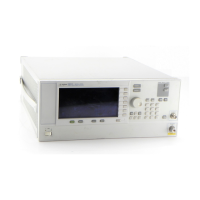
This section lists the major assemblies in the signal generator.
• A1 Keyboard page 3-10
• A2 Display page 3-10
• A2DS1 Backlight page 3-10
• A3 Power Switch page 3-10
• A4 Inverter page 3-10
• A5 Sampler page 3-12
• A6 Frac-N page 3-12
• A7 Reference (Standard) page 3-12
• A7 Reference (Option UNJ) page 3-12
• A8 Output page 3-12
• A9 YIG Driver page 3-12
• A10 ALC page 3-12
• A11 Pulse/Analog Modulation Generator (E8251A and E8254A Models Only) page 3-12
• A18 CPU page 3-12
• A18BT1 page 3-20
• A19 Power Supply page 3-12
• A20 SMI (Source Module Interface) page 3-16
• A21 Rear Panel Interface page 3-16
• A22 Line Module page 3-16
• AT1 115 dB Attenuator (Option 1E1) page 3-17
• A23 Low Band Coupler/Detector page 3-17
• A24 20 GHz High Band Coupler (E8241A and E8251A Models Only) page 3-17
• A24 40 GHz High Band Coupler (E8244A and E8254A Models Only) page 3-17
• A25 20 GHz High Band Detector (E8241A and E8251A Models Only) page 3-17
• A25 40 GHz High Band Detector (E8244A and E8254A Models Only) page 3-17
• A25B High Band Detector Bias Board page 3-17
• A26 MID (Microcircuit Interface Deck) page 3-17
• A27 40 GHz Doubler (E8244A and E8254A Models Only) page 3-17
• A28 YIG Oscillator page 3-18
• A29 20 GHz Doubler page 3-18
• A30 Modulation Filter with Standard Power page 3-18
• A30 Modulation Filter with High Power (Option 1EA) page 3-18
• A31 Motherboard page 3-14
• A32 10 MHz Crystal Oscillator (Option UNJ) page 3-16
•B1 Fanpage 3-16
• RF Output Connector page 3-51
• Front Panel page 3-38
• Outer and Inner Instrument Covers page 3-55

 Loading...


