Post-Repair Procedures
Post-Repair Procedures Matrix
4-2
Post-Repair Procedures Matrix
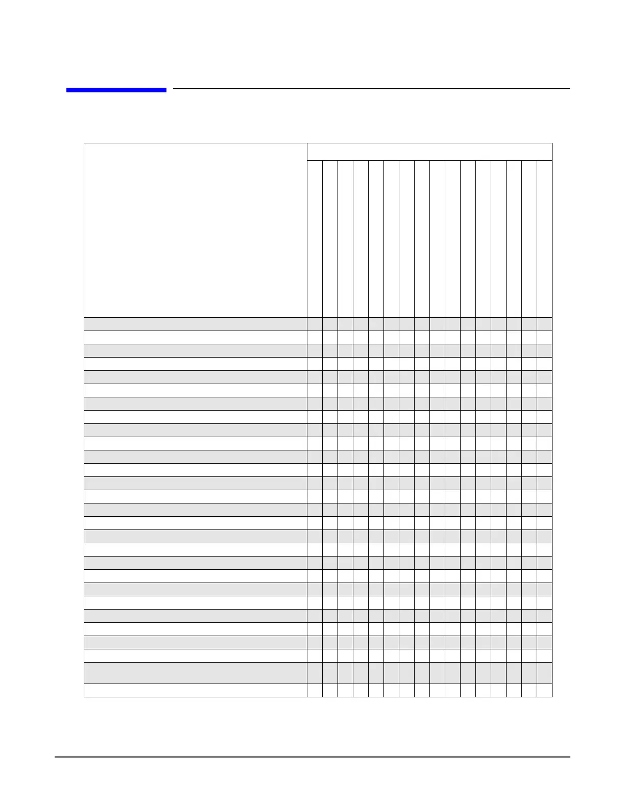
Table 4-1 Adjustments for Assemblies A1 through A20
Adjustments
The following adjustments are listed in
the order that they should be performed
for proper calibration.
Replaced Assembly
A1 Keyboard
A2 Display
A2DS1 Backlight
A3 Power Switch
A4 Inverter
A5 Sampler
A6 Frac-N
A7 Reference
A8 Output
A9 YIG Driver
A10 ALC
A11 Pulse/Analog Mod Gen
A18 CPU
A19 Power Supply
A20 SMI [Source Module Interface]
RF Output Connector
ADC Calibration
✔ ✔ ✔ ✔ ✔ ✔ ✔ ✔
YIG-Driver Pre-Tune Calibration
✔
VCO Bias Frac-N Calibration
✔
Internal Source Calibration
✔
AM Audio Path Offset Calibration
✔ ✔
KV vs. Frequency Calibration
✔
Timebase Calibration
✔
FM Scale Offset Calibration
✔✔✔
FM Path Offset Calibration
✔ ✔ ✔
FM In-band Offset Calibration
✔✔✔
FM Inverting Amplifier Offset Calibration
✔
FM 1/2 Path Ratio Gain Calibration
✔✔✔
Mod Source Relative Gain Calibration
✔ ✔ ✔
FM/PM Out-of-Band Calibration
✔✔✔
FM/PM YO Frequency Compensation Calibration
✔ ✔ ✔
DC FM Calibration
✔✔✔
Low Frequency Output Calibration
✔
External Input Peak Detector Calibration
✔
ALC Dynamic Calibration
✔ ✔
Power Flatness Calibration
✔✔ ✔
Attenuator Calibration, LowBand andHigh BandPower
Attenuator Calibration, High Band and High Power
Attenuator Calibration, Low Band and Low Power
Attenuator Calibration, High Band and Low Power
ALC Modulator Calibration
✔ ✔
AM Gain Calibration
✔✔✔
Gain Adjustment Bypass Calibration
(Frequencies </= 3.2 GHz)
✔ ✔
Pulse Width Calibration
✔✔

 Loading...


