Troubleshooting
Troubleshooting Assembly Level Problems
1-27
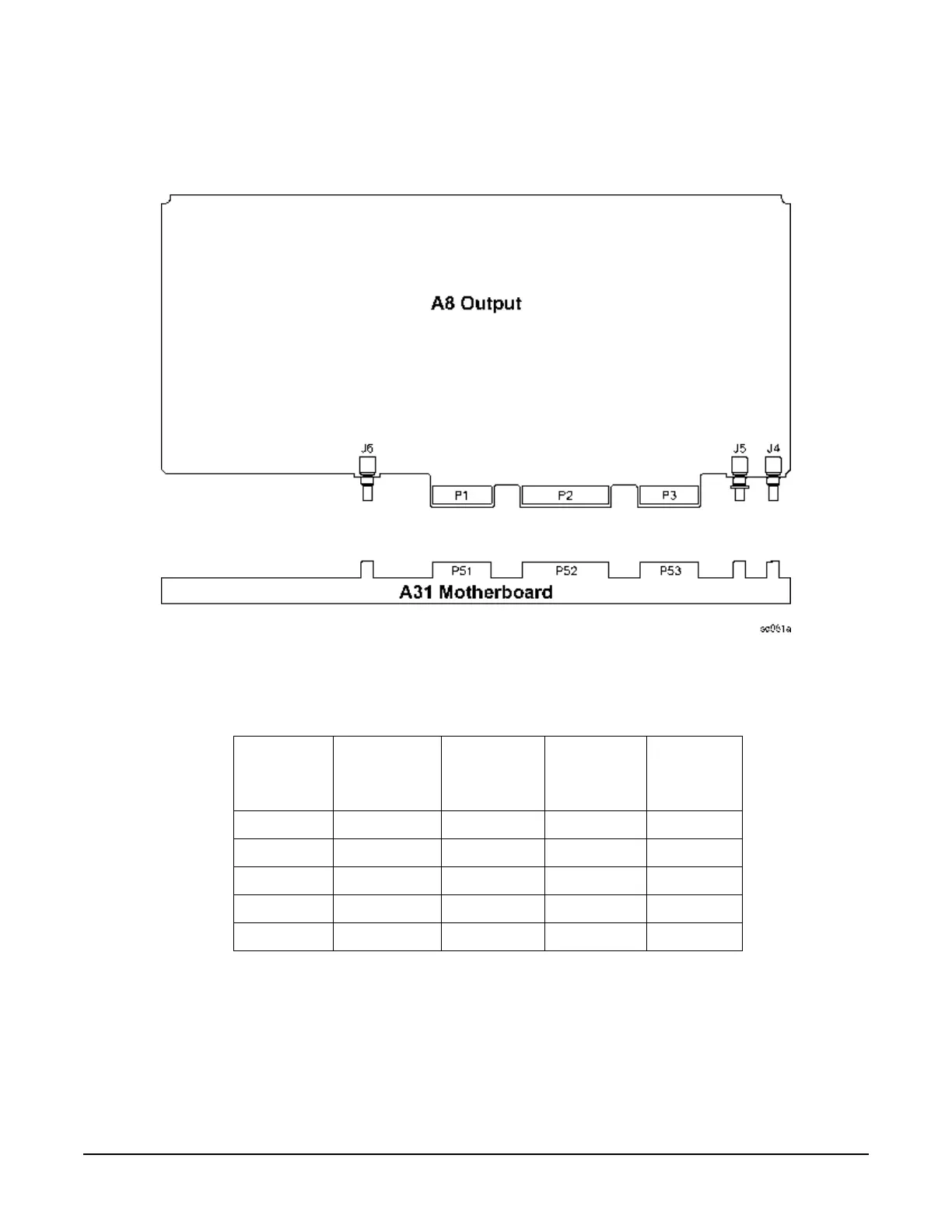
Self-Tests 4xx: A8 Output Self-Test Errors
Figure 1-4
Before proceeding to the reported self-test error code, check the voltages in Table1-19. If any
voltages are out of specification troubleshoot the supply problem first.
400 Ground and PTAT Test
1. Replace A8 Output.
401 Prelevel Loop Test
1. With the signal generator powered up carefully remove the A8 Output. Set the signal generator to 3 GHz
CW. Connect a spectrum analyzer to the A6 Frac-N RF output at J4 of the A8 Output. The signal at J4
Table 1-19
Supply
Voltage
(Vdc)
Connector
Pins
Minimum
Value
(Vdc)
Maximum
Value
(Vdc)
Origin
+15 P52-6, 21 +14.55 +15.45 Main Supply
-15 P52-2, 17 -14.55 -15.45 Main Supply
+5.2 P52-14, 29 +5.04 +5.36 Main Supply
+9 P52-5, 20 +8.82 +9.18 YIG Driver
-6 P52-3, 18 -5.88 -6.12 YIG Driver

 Loading...


