Troubleshooting
Troubleshooting Assembly Level Problems
1-43
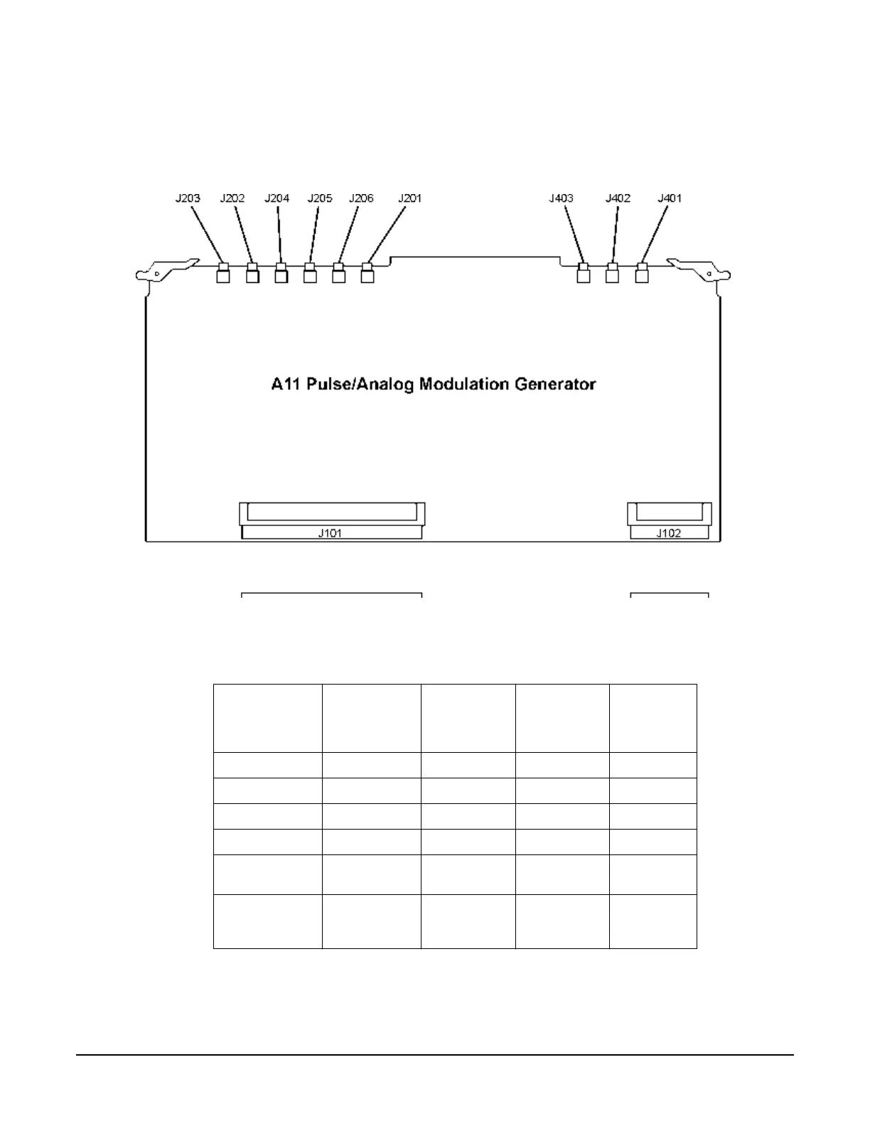
Self-Tests 13xx: A11 Analog/Pulse Modulation Generator Self-Test Errors
Figure 1-11
Before proceeding to the reported self-test error code, check the voltages in Table1-30. If any of
these voltages are out of specification troubleshoot the supply problem first.
1300 Power Supply
1. Replace the A7 Reference.
Table 1-30
Supply
Voltage
(Vdc)
Connector
Pins
Minimum
Value
(Vdc)
Maximum
Value
(Vdc)
Origin
+15 P132-28 +14.55 +15.45 Main Supply
-15 P132-3 -14.55 -15.45 Main Supply
+5.2 P132-2, 27 +5.04 +5.37 Main Supply
-5.2 P132-1, 26 -5.1 -5.3 YIG Driver
+5.2 Digital high P131-64, 65,
129, 130
+5.04 +5.36 Main Supply
+3.4 Digital Low P131-60, 61,
62, 63, 125,
126, 127, 128
+3.29 +3.5 Main Supply

 Loading...


