Troubleshooting
Overall Block Description
1-69
Overall Block Description
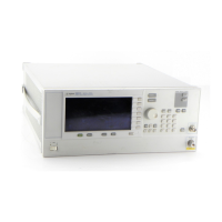
The objective of the overall block description is to provide a functional overview of the Performance Signal
Generator (PSG). Some of the functional blocks discussed are common to many types of instruments while
others are more specific to signal generators.
Common functions:
•Power Supply
•A18 CPU
•Input/Output Interface
Specific signal generator functions:
•Frequency Generation
•Output Power Level Control
•Modulation
A19 Power Supply
Voltages
The main power supply converts line voltage (120 Vac or 240 Vac) to regulated dc voltages. Some of the
required dc voltages are not directly provided by the main power supply and are generated by converting the
main power supply voltages. Converting is done on different assemblies and the adjusted voltages are routed
to the required assemblies.
Line Module
The line voltage is connected to the power supply through the A22 Line Module. The power supply
automatically detects and adjusts to different line voltages. Line voltage selection is not required. The power
supply has an internal line fuse. If the fuse opens, the power supply must be replaced.
Power supply thermal sensors
Two thermal sensors are used to prevent over heating of the signal generator. One sensor is internal to the
A19 Power Supply and the other is on the A8 Output. The amber and green LEDs on the front panel will blink
on and off when the signal generator goes into thermal shutdown.
A18 CPU
The A18 CPU controls all activities in the signal generator. The A18 CPU translates information entered from
the front panel keys, LAN, GPIB, or Auxilary Interface (RS-232) into machine level instructions and
communicates the instructions on the internal buses. The A18 CPU also monitors critical circuits for
unleveled and unlocked conditions and reports problems on the display.
Input/Output Interface
Located on the front panel are the A1 Keyboard, A2 Display, and A3 Power Switch. Input to the signal
generator is done through the front panel keypad and the display softkeys. Output from the signal generator
is done through the front panel display and the RF output connector. Above the power switch is an amber and

 Loading...


