Post-Repair Procedures
Post-Repair Procedures Matrix
4-3
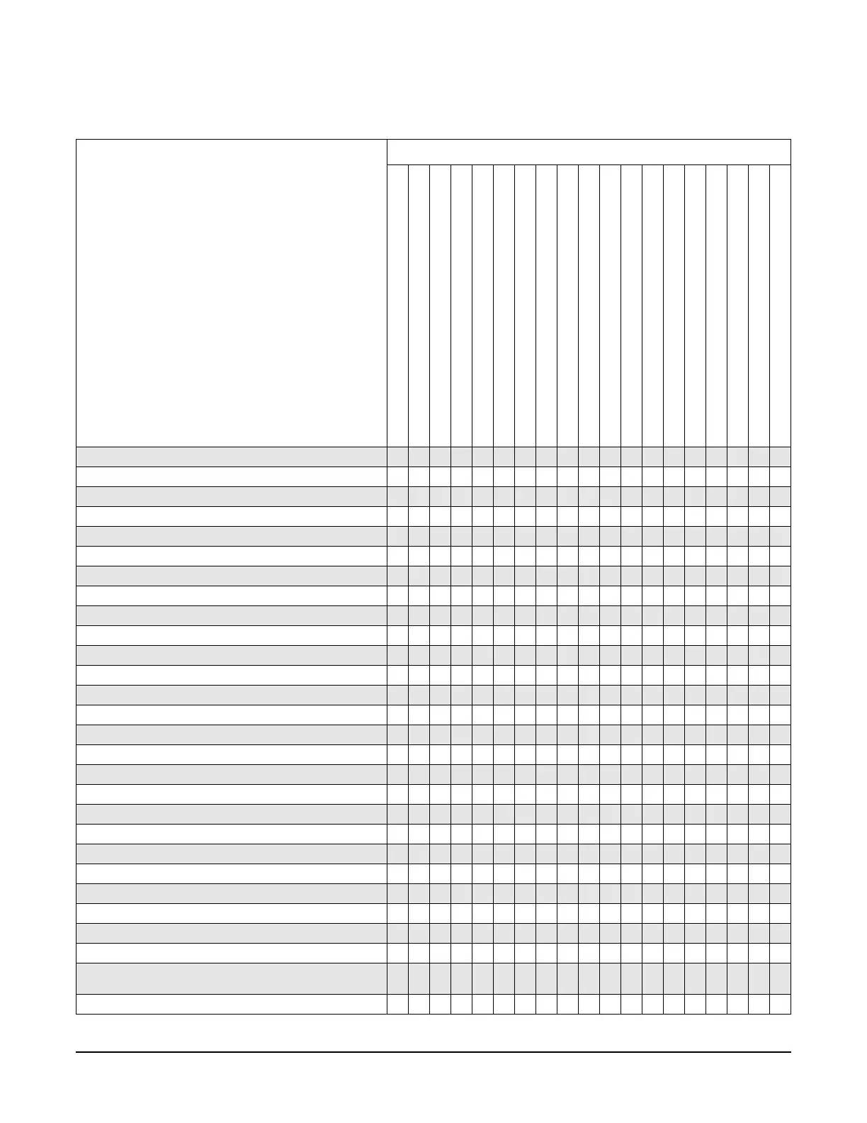
Table 4-2 Adjustments for Assemblies A21 through A32, B1, and RF Output Connector
Adjustments
The following adjustments are listed in
the order that they should be performed
for proper calibration.
Replaced Assembly
A21 Rear Panel
A22 Line Module
AT1 115 dB Attenuator
A23 Lowband Coupler/Detector
A24 20 GHz Coupler
A24 40 GHz Coupler
A25 20 GHz Detector
A25 40 GHz Detector
A25B Detector Bias Board
A26 MID
A27 40 GHz Doubler
A28 YIG Oscillator
A29 20 GHz Doubler
A30 Mod Filter with High Power (Option 1EA)
A30 Mod Filter with Standard Power
A31 Motherboard
A32 10 MHz Crystal Oscillator
B1 Fan
RF Output Connector
ADC Calibration
✔
YIG-Driver Pre-Tune Calibration
✔
VCO Bias Frac-N Calibration
Internal Source Calibration
AM Audio Path Offset Calibration
KV vs. Frequency Calibration
Timebase Calibration
✔
FM Scale Offset Calibration
✔
FM Path Offset Calibration
✔
FM In-band Offset Calibration
✔
FM Inverting Amplifier Offset Calibration
FM 1/2 Path Ratio Gain Calibration
✔
Mod Source Relative Gain Calibration
✔
FM/PM Out-of-Band Calibration
FM/PM YO Frequency Compensation Calibration
✔
DC FM Calibration
✔
Low Frequency Output Calibration
External Input Peak Detector Calibration
✔
ALC Dynamic Calibration
✔ ✔ ✔ ✔ ✔ ✔ ✔ ✔
Power Flatness Calibration
✔✔✔✔✔✔ ✔✔
Attenuator Calibration, Low Band and High Band Power
✔
Attenuator Calibration, High Band and High Power
✔
Attenuator Calibration, Low Band and Low Power
✔
Attenuator Calibration, High Band and Low Power
✔
ALC Modulator Calibration
✔ ✔
AM Gain Calibration
✔✔
Gain Adjustment Bypass Calibration
(Frequencies </= 3.2 GHz)
Pulse Width Calibration
✔✔

 Loading...


