Post-Repair Procedures
Post-Repair Procedures Matrix
4-4
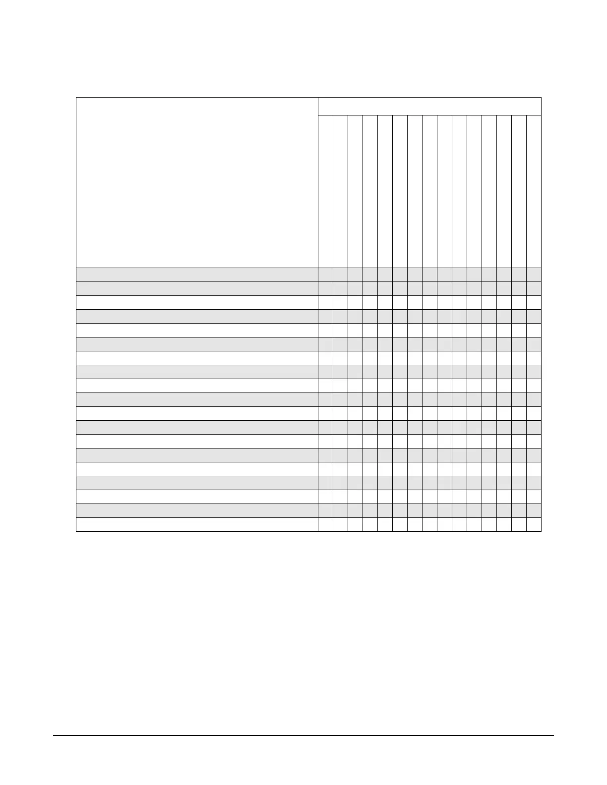
Table 4-3 Performance Tests for Assemblies A1 through A20
Performance Tests
The following performance tests are listed in
the order that they should be performed to
minimize changes in test equipment
configurations.
Replaced Assembly
A1 Keyboard
A2 Display
A2DS1 Backlight
A3 Power Switch
A4 Inverter
A5 Sampler
A6 Frac-N
A7 Reference
A8 Output
A9 YIG Driver
A10 ALC
A11 Pulse/Analog Mod Gen
A18 BT1
A19 Power Supply
A20 SMI [Source Module Interface]
Self Tests
✔ ✔ ✔ ✔ ✔ ✔ ✔ ✔ ✔ ✔ ✔ ✔ ✔ ✔ ✔
Maximum Leveled Output Power
✔ ✔ ✔
Power Level Accuracy
✔✔
Internal Pulse Modulation Level Accuracy
✔ ✔
Internal Pulse Modulation Rise/Fall Time
✔✔
Internal Pulse Modulation Minimum Pulse Width
✔ ✔ ✔
DC FM Carrier Offset
✔✔
External AM Frequency Response
✔ ✔ ✔
Internal FM Frequency Response
✔✔✔
External Phase Modulation Frequency Response
✔ ✔ ✔
Internal FM Distortion
✔✔
Internal Phase Modulation Distortion
✔ ✔
External FM Deviation Accuracy
✔✔✔
Internal Phase Modulation Deviation Accuracy
✔ ✔ ✔
External Pulse Modulation ON/OFF Ratio
✔✔
Harmonic Spurious
✔ ✔
Sub-Harmonic Spurious
✔
Non-Harmonic Spurious
✔ ✔ ✔ ✔
Single-Sideband Phase Noise
✔✔✔✔✔

 Loading...


