Troubleshooting
Troubleshooting Assembly Level Problems
1-41
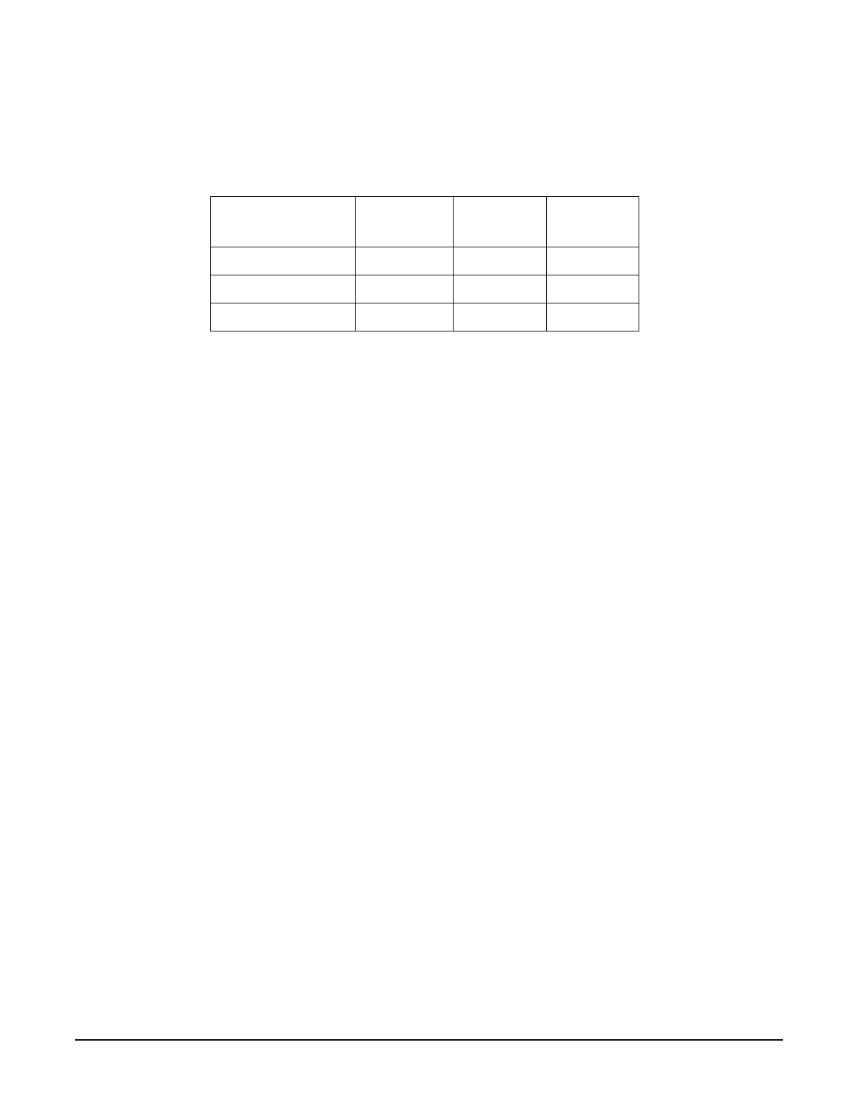
run self-test 1200. If the test passes after disconnecting one or more microcircuits, replace the
microcircuit. If self-test still fails after disconnecting all the microcircuits, replace the A26 MID. The table
below shows the power supply each microcircuit.
1201 Mod Filter
1. Disconnect the cable coming from the A23 Low Band Coupler/Detector to the A30 Modulation Filter.
Connect a spectrum analyzer to the cable. Tune the source across the low band frequencies (250 kHz to
3.2 GHz) and record the lowest power level.
2. Disconnect the cable coming from the A29 20 GHz Doubler and connect a spectrum analyzer to the cable.
Tune the source across the A29 20 GHz Doubler band of frequencies (3.2 GHz to 20 GHz) noting the lowest
power level.
3. Compare the levels recorded to the levels shown on the RF Path Block.
4. If all power levels are good, replace the A30 Modulation Filter.
5. If the power level in either path is bad, troubleshoot that path.
6. If the power levels in both paths are bad, check the signal levels out of the A28 YIG Oscillator.
1202 A29 20 GHz Doubler
1. Disconnect the cable coming from the A28 YIG Oscillator to the A29 20 GHz Doubler and connect a
spectrum analyzer to the cable. Tune the source frequency across the A28 YIG Oscillator range (3.2 GHz
to 10 GHz) noting the lowest power level.
2. Compare the levels recorded to the levels shown on the RF Path Block.
3. If the power level is good, replace the A29 20 GHz Doubler.
4. If the power level is bad, replace the A28 YIG Oscillator.
1203 40 GHz Doubler
1. Disconnect the 0 to 20 GHz cable coming from the A30 Modulation Filter to the A27 40 GHz Doubler and
connect a spectrum analyzer to the cable. Tune the source from 250 kHz to 20 GHz and record the lowest
power level.
2. Disconnect the 10 to 20 GHz cable coming from the A30 Modulation Filter and connect a spectrum
analyzer to the cable. Tune the source from 20 GHz to 40 GHz noting the lowest power level.
3. Compare the levels recorded to the levels shown on the RF Path Block.
4. If all power levels are good, replace the A27 40 GHz Doubler.
5. If the power level either or both paths is bad, troubleshoot the path.
Table 1-29
Microcircuit A26 MID
connector
+12 Vdc +8 Vdc
A30 Modulation Filter J31
✔✔
A29 20 GHz Doubler J32
✔✔
A27 40 GHz Doubler J33
✔

 Loading...


